Showing posts with label cisco. Show all posts

Wednesday, 25 January 2012

Some Revision - EIGRP offset lists

Every so often when reading around the internet you come across a post/email with a network related problem that makes you think "hmmmm i've never had to do that" or "that sounds like an interesting problem" - I'll lab it and see if I can find the answer.

Combine that with an area that I do not normally need to work in (EIGRP) and there you go a blog post in the making!


So here is the scenrio:

You are a network admin that looks after three sites, one main site where your offices are and two datacentres.

You have 2x100mbit links to each datacentre and the databcentres have 1x1Gbit link.


The problem:

Traffic to a certain network/host at datacentre 2 is overloading the link so we as the network admins have been asked if we can use the excess capacity on the link to datacentre 1 to spread the traffic.


First we setup the lab:

R1

interface Loopback0
ip address 192.168.101.1 255.255.255.0
!
interface Loopback1
ip address 1.1.1.1 255.255.255.255
!
interface FastEthernet0/0
ip address 192.168.12.1 255.255.255.0
duplex auto
speed auto
!
interface FastEthernet0/1
ip address 192.168.13.1 255.255.255.0
duplex auto
speed auto
!
router eigrp 100
network 192.168.12.0
network 192.168.13.0
network 192.168.101.0
no auto-summary
!


R2

interface Loopback0
ip address 10.100.10.1 255.255.255.0
!
interface Loopback1
ip address 2.2.2.2 255.255.255.255
!
interface FastEthernet0/0
ip address 192.168.12.2 255.255.255.0
duplex auto
speed auto
!
interface FastEthernet0/1
ip address 192.168.23.2 255.255.255.0
duplex auto
speed auto
!
router eigrp 100
network 10.100.10.0 0.0.0.255
network 192.168.12.0
network 192.168.23.0
no auto-summary
!


R3


interface Loopback0
ip address 10.200.10.1 255.255.255.0
!
interface Loopback3
ip address 3.3.3.3 255.255.255.255
!
interface FastEthernet0/0
ip address 192.168.13.3 255.255.255.0
duplex auto
speed auto
!
interface FastEthernet0/1
ip address 192.168.23.3 255.255.255.0
duplex auto
speed auto
!
router eigrp 100
network 3.3.3.3 0.0.0.0
network 10.200.10.0 0.0.0.255
network 192.168.13.0
network 192.168.23.0
no auto-summary
!


Now the offset lists:
R1

ip access-list standard LOOPBACK
permit 3.3.3.3

router eigrp 100
offset-list LOOPBACK in 4000 FastEthernet0/1


Confirming...

R1


R1#sh ip route
Codes: C - connected, S - static, R - RIP, M - mobile, B - BGP
D - EIGRP, EX - EIGRP external, O - OSPF, IA - OSPF inter area
N1 - OSPF NSSA external type 1, N2 - OSPF NSSA external type 2
E1 - OSPF external type 1, E2 - OSPF external type 2
i - IS-IS, su - IS-IS summary, L1 - IS-IS level-1, L2 - IS-IS level-2
ia - IS-IS inter area, * - candidate default, U - per-user static route
o - ODR, P - periodic downloaded static route

Gateway of last resort is not set

C 192.168.12.0/24 is directly connected, FastEthernet0/0
1.0.0.0/32 is subnetted, 1 subnets
C 1.1.1.1 is directly connected, Loopback1
C 192.168.13.0/24 is directly connected, FastEthernet0/1
3.0.0.0/32 is subnetted, 1 subnets
D 3.3.3.3 [90/158720] via 192.168.12.2, 00:03:14, FastEthernet0/0
10.0.0.0/24 is subnetted, 2 subnets
D 10.100.10.0 [90/156160] via 192.168.12.2, 00:05:48, FastEthernet0/0
D 10.200.10.0 [90/156160] via 192.168.13.3, 00:05:48, FastEthernet0/1
D 192.168.23.0/24 [90/30720] via 192.168.13.3, 00:05:48, FastEthernet0/1
[90/30720] via 192.168.12.2, 00:05:48, FastEthernet0/0
C 192.168.101.0/24 is directly connected, Loopback0


Note this bit:

3.0.0.0/32 is subnetted, 1 subnets
D 3.3.3.3 [90/158720] via 192.168.12.2, 00:03:14, FastEthernet0/0

The succesor route is from 192.168.12.2 without the offset list it would be 192.168.13.3.

Here is the output from sh ip eigrp topology all-links

R1#sh ip eigrp topology all-links
IP-EIGRP Topology Table for AS(100)/ID(192.168.101.1)

Codes: P - Passive, A - Active, U - Update, Q - Query, R - Reply,
r - reply Status, s - sia Status

P 3.3.3.3/32, 1 successors, FD is 158720, serno 9
via 192.168.12.2 (158720/156160), FastEthernet0/0
via 192.168.13.3 (160160/132256), FastEthernet0/1
P 192.168.101.0/24, 1 successors, FD is 128256, serno 3
via Connected, Loopback0
P 10.100.10.0/24, 1 successors, FD is 156160, serno 6
via 192.168.12.2 (156160/128256), FastEthernet0/0
via 192.168.13.3 (158720/156160), FastEthernet0/1
P 192.168.12.0/24, 1 successors, FD is 28160, serno 1
via Connected, FastEthernet0/0
P 192.168.13.0/24, 1 successors, FD is 28160, serno 2
via Connected, FastEthernet0/1
P 192.168.23.0/24, 2 successors, FD is 30720, serno 7
via 192.168.12.2 (30720/28160), FastEthernet0/0
via 192.168.13.3 (30720/28160), FastEthernet0/1
P 10.200.10.0/24, 1 successors, FD is 156160, serno 4
via 192.168.13.3 (156160/128256), FastEthernet0/1
via 192.168.12.2 (158720/156160), FastEthernet0/0


Problem solved :)

Wednesday, 13 July 2011

Vyatta - Hub And Spoke - OSPF over GRE over IPSEC

So my planned more frequent updates to my blog did not exactly go to plan.

Oh well :) I'm posting today with a good one.

Today we are once again playing the role of a Managed Service Provider who is providing a Managed Cloud Service + Firewall the customer however has two Cisco 3745 routers.

We have two Hubs MSP-R1 and MSP-R2 both Vyatta and R1,R2 both IOS.


Here is a picture:


MSP-R1 - Set Up Interfaces:

interfaces {
ethernet eth0 {
address 213.111.222.1/24
description INTERNET
duplex auto
firewall {
in {
name WAN_IN
}
local {
name VYATTA_IN
}
}
hw-id 08:00:27:a2:7a:a9
smp_affinity auto
speed auto
}
ethernet eth1 {
address 192.168.45.1/24
description TRMSPTED
duplex auto
hw-id 08:00:27:03:40:e0
ip {
ospf {
dead-interval 40
hello-interval 10
priority 1
retransmit-interval 5
transmit-delay 1
}
}
smp_affinity auto
speed auto
}
ethernet eth2 {
duplex auto
hw-id 08:00:27:68:d2:71
smp_affinity auto
speed auto
}
loopback lo {
address 1.1.1.1/32
}
tunnel tun0 {
address 10.10.45.1/30
description Linkto R2
encapsulation gre
ip {
ospf {
dead-interval 6
hello-interval 2
priority 1
retransmit-interval 5
transmit-delay 1
}
}
local-ip 1.1.1.1
multicast disable
remote-ip 2.2.2.2
ttl 255
}
tunnel tun1 {
address 10.10.45.5/30
description Linkto R2
encapsulation gre
ip {
ospf {
dead-interval 6
hello-interval 2
priority 1
retransmit-interval 5
transmit-delay 1
}
}
local-ip 1.1.1.1
multicast disable
remote-ip 3.3.3.3
ttl 255
}
}


MSP-R2 - Set Up Interfaces:

interfaces {
ethernet eth0 {
address 213.111.222.10/24
description INTERNET
duplex auto
hw-id 08:00:27:31:80:53
smp_affinity auto
speed auto
}
ethernet eth1 {
address 192.168.45.1/24
duplex auto
hw-id 08:00:27:40:cd:1e
ip {
ospf {
dead-interval 40
hello-interval 10
priority 1
retransmit-interval 5
transmit-delay 1
}
}
smp_affinity auto
speed auto
}
loopback lo {
address 10.10.10.10/32
}
tunnel tun0 {
address 10.10.45.9/30
description Linkto R1
encapsulation gre
ip {
ospf {
dead-interval 6
hello-interval 2
priority 1
retransmit-interval 5
transmit-delay 1
}
}
local-ip 10.10.10.10
multicast disable
remote-ip 2.2.2.2
ttl 255
}
tunnel tun1 {
address 10.10.45.13/30
description LinkTo R2
encapsulation gre
ip {
ospf {
dead-interval 6
hello-interval 2
priority 1
retransmit-interval 5
transmit-delay 1
}
}
local-ip 10.10.10.10
multicast disable
remote-ip 3.3.3.3
ttl 255
}
}


R1 - Spoke set up interfaces:

interface Loopback0
ip address 2.2.2.2 255.255.255.255
!
interface Tunnel0
ip address 10.10.45.2 255.255.255.252
ip ospf hello-interval 2
ip ospf dead-interval 6
tunnel source Loopback0
tunnel destination 1.1.1.1
!
interface Tunnel1
ip address 10.10.45.10 255.255.255.252
ip ospf hello-interval 2
ip ospf dead-interval 6
tunnel source Loopback0
tunnel destination 10.10.10.10
!
interface FastEthernet0/0
ip address 76.1.1.2 255.255.255.0
duplex auto
speed auto
crypto map MSP-MAP
!
interface FastEthernet0/1
ip address 10.101.0.1 255.255.255.0
duplex auto
speed auto
!


R2 - Spoke set up interfaces:

interface Loopback0
ip address 3.3.3.3 255.255.255.255
!
interface Tunnel0
ip address 10.10.45.6 255.255.255.252
ip ospf hello-interval 2
ip ospf dead-interval 6
tunnel source Loopback0
tunnel destination 1.1.1.1
!
interface Tunnel1
ip address 10.10.45.14 255.255.255.252
ip ospf hello-interval 2
ip ospf dead-interval 6
tunnel source Loopback0
tunnel destination 10.10.10.10
!
interface FastEthernet0/0
ip address 76.2.2.2 255.255.255.0
duplex auto
speed auto
no cdp enable
crypto map MSP-MAP
!
interface FastEthernet0/1
ip address 10.202.0.1 255.255.255.0
duplex auto
speed auto
!


MSP-R1 Set up VPN:

vpn {
ipsec {
esp-group ESP-1W {
compression disable
lifetime 3600
mode tunnel
pfs enable
proposal 1 {
encryption 3des
hash sha1
}
}
ike-group IKE-1W {
dead-peer-detection {
action restart
interval 30
timeout 30
}
lifetime 28800
proposal 1 {
encryption 3des
hash sha1
}
}
ipsec-interfaces {
interface eth0
}
nat-networks {
allowed-network 0.0.0.0/0 {
exclude 192.168.45.0/24
}
}
nat-traversal enable
site-to-site {
peer 76.1.1.2 {
authentication {
mode pre-shared-secret
pre-shared-secret letmein
}
ike-group IKE-1W
local-ip 213.111.222.1
tunnel 1 {
allow-nat-networks disable
allow-public-networks disable
esp-group ESP-1W
local-subnet 1.1.1.1/32
remote-subnet 2.2.2.2/32
}
}
peer 76.2.2.2 {
authentication {
mode pre-shared-secret
pre-shared-secret letmein
}
ike-group IKE-1W
local-ip 213.111.222.1
tunnel 1 {
allow-nat-networks disable
allow-public-networks disable
esp-group ESP-1W
local-subnet 1.1.1.1/32
remote-subnet 3.3.3.3/32
}
}
}
}
}

MSP-R2 Set up VPN:

vpn {
ipsec {
esp-group ESP-1W {
compression disable
lifetime 3600
mode tunnel
pfs enable
proposal 1 {
encryption 3des
hash sha1
}
}
ike-group IKE-1W {
dead-peer-detection {
action restart
interval 30
timeout 30
}
lifetime 28800
proposal 1 {
encryption 3des
hash sha1
}
}
ipsec-interfaces {
interface eth0
}
nat-networks {
allowed-network 0.0.0.0/0 {
exclude 192.168.45.0/24
}
}
nat-traversal enable
site-to-site {
peer 76.1.1.2 {
authentication {
mode pre-shared-secret
pre-shared-secret letmein
}
ike-group IKE-1W
local-ip 213.111.222.10
tunnel 1 {
allow-nat-networks disable
allow-public-networks disable
esp-group ESP-1W
local-subnet 10.10.10.10/32
remote-subnet 2.2.2.2/32
}
}
peer 76.2.2.2 {
authentication {
mode pre-shared-secret
pre-shared-secret letmein
}
ike-group IKE-1W
local-ip 213.111.222.10
tunnel 1 {
allow-nat-networks disable
allow-public-networks disable
esp-group ESP-1W
local-subnet 10.10.10.10/32
remote-subnet 3.3.3.3/32
}
}
}
}
}


R1 Set up VPN:

!
crypto isakmp policy 100
encr 3des
authentication pre-share
group 2
crypto isakmp key letmein address 213.111.222.1
crypto isakmp key letmein address 213.111.222.10
!
crypto ipsec transform-set MSP-TRANSFORM esp-3des esp-sha-hmac
!
crypto map MSP-MAP 10 ipsec-isakmp
set peer 213.111.222.1
set transform-set MSP-TRANSFORM
match address 101
crypto map MSP-MAP 20 ipsec-isakmp
set peer 213.111.222.10
set transform-set MSP-TRANSFORM
match address 102
!
!
access-list 101 permit 0 host 2.2.2.2 host 1.1.1.1
access-list 102 permit 0 host 2.2.2.2 host 10.10.10.10
!


R2 Set up VPN:

crypto isakmp policy 100
encr 3des
authentication pre-share
group 2
crypto isakmp key letmein address 213.111.222.1
crypto isakmp key letmein address 213.111.222.10
!
!
crypto ipsec transform-set MSP-TRANSFORM esp-3des esp-sha-hmac
!
crypto map MSP-MAP 10 ipsec-isakmp
set peer 213.111.222.1
set transform-set MSP-TRANSFORM
match address 101
crypto map MSP-MAP 20 ipsec-isakmp
set peer 213.111.222.10
set transform-set MSP-TRANSFORM
match address 102
!
!
access-list 101 permit 0 host 3.3.3.3 host 1.1.1.1
access-list 102 permit 0 host 3.3.3.3 host 10.10.10.10
!


MSP-R1 - OSPF setup

protocols {
ospf {
area 0 {
network 10.10.45.0/30
network 192.168.45.0/24
network 10.10.45.4/30
}
parameters {
abr-type cisco
router-id 1.1.1.1
}
}


MSP-R2 - OSPF setup

protocols {
ospf {
area 0 {
network 192.168.45.0/24
network 10.10.45.8/30
network 10.10.45.12/30
}
parameters {
abr-type cisco
router-id 10.10.10.10
}
}


R1 - OSPF setup

router ospf 1
router-id 2.2.2.2
log-adjacency-changes
network 10.10.45.0 0.0.0.3 area 0
network 10.10.45.8 0.0.0.3 area 0
network 10.101.0.0 0.0.0.255 area 0
maximum-paths 6
!


R2 - OSPF setup

router ospf 1
router-id 3.3.3.3
log-adjacency-changes
network 10.10.45.4 0.0.0.3 area 0
network 10.10.45.12 0.0.0.3 area 0
network 10.202.0.0 0.0.0.255 area 0
maximum-paths 6
!


Proof is in the pudding -


Routing Tables


R1:

Gateway of last resort is 76.1.1.1 to network 0.0.0.0

2.0.0.0/32 is subnetted, 1 subnets
C 2.2.2.2 is directly connected, Loopback0
O 192.168.43.0/24 [110/11121] via 10.10.43.9, 00:00:01, Tunnel1
[110/11121] via 10.10.43.1, 00:00:01, Tunnel0
76.0.0.0/24 is subnetted, 1 subnets
C 76.1.1.0 is directly connected, FastEthernet0/0
10.0.0.0/8 is variably subnetted, 6 subnets, 2 masks
C 10.10.43.8/30 is directly connected, Tunnel1
O 10.10.43.12/30 [110/11121] via 10.10.43.9, 00:00:01, Tunnel1
C 10.10.43.0/30 is directly connected, Tunnel0
O 10.10.43.4/30 [110/11121] via 10.10.43.1, 00:00:01, Tunnel0
C 10.101.0.0/24 is directly connected, FastEthernet0/1
O 10.202.0.0/24 [110/11122] via 10.10.43.1, 00:00:01, Tunnel0
[110/11122] via 10.10.43.9, 00:00:01, Tunnel1
S* 0.0.0.0/0 [1/0] via 76.1.1.1


R2:

Gateway of last resort is 76.2.2.1 to network 0.0.0.0

3.0.0.0/32 is subnetted, 1 subnets
C 3.3.3.3 is directly connected, Loopback0
O 192.168.43.0/24 [110/11121] via 10.10.43.5, 00:01:29, Tunnel0
[110/11121] via 10.10.43.13, 00:01:29, Tunnel1
76.0.0.0/24 is subnetted, 1 subnets
C 76.2.2.0 is directly connected, FastEthernet0/0
10.0.0.0/8 is variably subnetted, 6 subnets, 2 masks
O 10.10.43.8/30 [110/11121] via 10.10.43.13, 00:01:29, Tunnel1
C 10.10.43.12/30 is directly connected, Tunnel1
O 10.10.43.0/30 [110/11121] via 10.10.43.5, 00:01:29, Tunnel0
C 10.10.43.4/30 is directly connected, Tunnel0
O 10.101.0.0/24 [110/11122] via 10.10.43.5, 00:01:29, Tunnel0
[110/11122] via 10.10.43.13, 00:01:29, Tunnel1

Wednesday, 3 March 2010

Wired 802.1x Port Authentication with Certificate Auto Enrolment

As we all know compliance is one of the biggest issues facing companies at the moment leading some IT departments to take a look at 802.1x as a way of controlling and securing access to their wired networks.

The main reason for this post is there are a few articles out there that have mis-truths and incorrect facts within them, often due to them having not implemented the technologies themselves.

Here is the lab:


So here we go:
Part1
GNS Setup
VMware Workstation Setup
Domain Controller Setup

Wired 802.1x Port Authentication with Certificate Auto Enrolment Part1 from Richard Vimeo on Vimeo.


Part 2
Certificate Service Setup
Certifcate Templates
Switch Setup
IAS/Radius install
Auto Enrolment

Wired 802.1x Port Authentication with Certificate Auto Enrolment Part2 from Richard Vimeo on Vimeo.


Part 3
IAS Setup
Extra Switch Config
Flicking the Switch! (on the switch)
Testing
Event Log Messages

Wired 802.1x Port Authentication with Certificate Auto Enrolment Part3 from Richard Vimeo on Vimeo.

Tuesday, 24 November 2009

If Security Is Obscurity...

Then these companies need help:

http://shodan.surtri.com/?q=cisco-IOS


Shodan is a cool new search engine that takes google-hacking to the next level.

Monday, 9 November 2009

Testing QoS with Cisco Call Manager and SIP,RTP - How To

This is the practical to this lab: here


Setting up basic IP connectivity:
R1

!
interface FastEthernet0/0
description ToLan
ip address 192.168.10.254 255.255.255.0
duplex auto
speed auto
!
!
interface Serial0/0.123 multipoint
bandwidth 110
ip address 192.168.0.1 255.255.255.0
ip ospf network point-to-multipoint
snmp trap link-status
frame-relay map ip 192.168.0.2 122 broadcast
frame-relay map ip 192.168.0.3 123 broadcast
no frame-relay inverse-arp
!
!
router ospf 1
router-id 1.1.1.1
log-adjacency-changes
network 1.1.1.1 0.0.0.0 area 1
network 192.168.0.0 0.0.0.255 area 0
network 192.168.10.0 0.0.0.255 area 1
!


R2

!
interface FastEthernet0/0
description ToLan
ip address 192.168.10.254 255.255.255.0
duplex auto
speed auto
!
!
interface Serial0/0.123 multipoint
bandwidth 110
ip address 192.168.0.1 255.255.255.0
ip ospf network point-to-multipoint
snmp trap link-status
frame-relay map ip 192.168.0.2 122 broadcast
frame-relay map ip 192.168.0.3 123 broadcast
no frame-relay inverse-arp
!
!
router ospf 1
router-id 1.1.1.1
log-adjacency-changes
network 1.1.1.1 0.0.0.0 area 1
network 192.168.0.0 0.0.0.255 area 0
network 192.168.10.0 0.0.0.255 area 1
!


R3

!
interface FastEthernet0/0
ip address 192.168.3.254 255.255.255.0
duplex auto
speed auto
!
!
interface Serial0/0.321 multipoint
bandwidth 110
ip address 192.168.0.3 255.255.255.0
ip ospf network point-to-multipoint
frame-relay map ip 192.168.0.1 321 broadcast
frame-relay map ip 192.168.0.2 321 broadcast
!
!
router ospf 1
router-id 3.3.3.3
log-adjacency-changes
network 3.3.3.3 0.0.0.0 area 3
network 192.168.0.0 0.0.0.255 area 0
network 192.168.3.0 0.0.0.255 area 3
!


Set up DHCP for Call Manager/TFTP
R1

ip dhcp excluded-address 192.168.10.1
ip dhcp excluded-address 192.168.10.100
ip dhcp excluded-address 192.168.10.254
!
ip dhcp pool POOL1
network 192.168.10.0 255.255.255.0
option 66 ip 192.168.10.100
default-router 192.168.10.254
!


(Pretty much the same on each router)


Now the important Stuff - QoS for SIP and RTP...

First the ACLs:

!
!Control is for SIP messages
ip access-list extended VOIP-CONTROL-ACL
permit tcp any any eq 5060
permit tcp any eq 5060 any
permit tcp any any eq 6970
permit tcp any eq 6970 any
! RTP is for the actual voices going down the line
ip access-list extended VOIP-RTP-ACL
permit udp any any eq 5060
permit udp any eq 5060 any
permit udp any any range 16384 32767
permit ip any any dscp ef
!


Now the Class Maps:

!
class-map match-any VOIP-CONTROL-CLASS
match access-group name VOIP-CONTROL-ACL
class-map match-any VOIP-RTP-CLASS
match access-group name VOIP-RTP-ACL
!


Now the Policy Maps:

!
policy-map VOIP
class VOIP-RTP-CLASS
priority 70
class VOIP-CONTROL-CLASS
bandwidth 8
class class-default
fair-queue
!


Map Class - Frame Relay:

!
map-class frame-relay FRAME-CLASS
!Provided by ISP
frame-relay cir 110000
!Set Tc to 10ms or 0.01 sec
frame-relay bc 1100
frame-relay be 0
!If you get a BECN set to this rate
frame-relay mincir 110000
!Remember to place this on both ends
frame-relay fragment 120
!Policy map
service-policy output VOIP
!


A few little extras(needed):

!
interface Serial0/0
bandwidth 400
no ip address
encapsulation frame-relay
frame-relay traffic-shaping
no frame-relay inverse-arp
frame-relay ip rtp header-compression
!
!
interface Serial0/0.123 multipoint
bandwidth 110
ip address 192.168.0.1 255.255.255.0
ip ospf network point-to-multipoint
snmp trap link-status
frame-relay class FRAME-CLASS
frame-relay map ip 192.168.0.2 122 broadcast
frame-relay map ip 192.168.0.3 123 broadcast
no frame-relay inverse-arp
!


Here is a video of the lab set up and me trying to break it!

Testing Quality of Service with Cisco Call Manager,VoIP from Richard Vimeo on Vimeo.


Here are the iPerf options I am using:
Server UDP:

iperf.exe -us -n 128m -i5

Client UDP:

iperf.exe -uc 192.168.2.3 -b256k -n 1G -i5 -d


*Remember if you wish to test DSCP tags try the "-s" options to tag the packets for example: "-s ef"

Sunday, 8 November 2009

Testing QoS with Cisco Call Manager and SIP,RTP

Hello again all,

Created a nice little lab here:


I plan to not only get up QoS but really stress test it using iperf to see if it works!

Tuesday, 27 October 2009

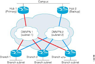
DMVPN - Dual Hub and Dual Spoke with HSRP - Howto

Hi again,

This is the practical to this lab: here

First the boring stuff, setting up IP connectivity:

R1

interface FastEthernet1/0
description WAN
ip address 10.0.1.1 255.255.255.0
interface FastEthernet1/1
!
description LAN
ip address 192.168.1.1 255.255.255.0
!
interface Loopback0
ip address 1.1.1.1 255.255.255.255
!
ip route 0.0.0.0 0.0.0.0 10.0.1.99
!


R2

interface FastEthernet1/1
description lan
ip address 192.168.1.2 255.255.255.0
!
interface FastEthernet1/0
description wan
ip address 10.0.2.2 255.255.255.0
!
interface Loopback0
ip address 2.2.2.2 255.255.255.255
!
ip route 0.0.0.0 0.0.0.0 10.0.2.99
!


R10

!
interface Loopback0
ip address 10.10.10.10 255.255.255.255
!
!
interface FastEthernet1/0
description wan
ip address 10.0.10.10 255.255.255.0
!
interface FastEthernet1/1
description lan
ip address 192.168.2.10 255.255.255.0
delay 1000
!


R11

interface Loopback0
ip address 11.11.11.11 255.255.255.255
!
interface FastEthernet1/0
description wan
ip address 10.0.11.11 255.255.255.0
!
interface FastEthernet1/1
description lan
ip address 192.168.2.11 255.255.255.0
delay 1050
!
ip route 0.0.0.0 0.0.0.0 10.0.11.99
!

R20

!
interface Loopback0
ip address 20.20.20.20 255.255.255.255
!
interface FastEthernet1/0
description wan
ip address 10.0.20.20 255.255.255.0
!
interface FastEthernet1/1
description lan
ip address 192.168.3.20 255.255.255.0
!
ip route 0.0.0.0 0.0.0.0 10.0.20.99
!


Let start with HSRP on Hubs:

R1

interface FastEthernet1/1
description LAN
ip address 192.168.1.1 255.255.255.0
delay 1000
duplex full
speed auto

!virtual ip
standby 1 ip 192.168.1.254
!Virtual set priority for this router higher than R2
standby 1 priority 20
!If R1 has a highier priority become the active router
standby 1 preempt
standby 1 name HAGroup
!If Fa1/0 fails R1 is useless and needs to become standby
standby 1 track FastEthernet1/0

!


R2

interface FastEthernet1/1
description lan
ip address 192.168.1.2 255.255.255.0
delay 1050
duplex auto
speed auto
standby 1 ip 192.168.1.254
standby 1 priority 19
standby 1 preempt
standby 1 name HAGroup
standby 1 track FastEthernet1/0
!


The above setup is almost identical at Site2 (the other site with HSRP)

Now on to the Tunnels and the DMVPN networks itself. Here is the basic layout of the network:


As you can see, we are infact running two DMVPN networks, and each spoke as an interface to each network.

Lets do the Hubs first:

R1


interface Tunnel0
!IP of tunnel interface
ip address 172.12.123.1 255.255.255.0
!Stop IP from taking "shortcuts"
no ip redirects
ip mtu 1400
ip nhrp map multicast dynamic
!Unique to the network, same number on each hub,spoke
ip nhrp network-id 1
ip nhrp holdtime 450
ip tcp adjust-mss 1360
!Needed for EIGRP
no ip split-horizon eigrp 100
!Tweak EIGRP metrics to prefer this router
delay 1000
!Tunnels out interface
tunnel source FastEthernet1/0
!Set tunnel mode
tunnel mode gre multipoint
!Each tunnel has its own "password"
tunnel key 100000
!Add IPSec
tunnel protection ipsec profile TUN-PROFILE


Notice that R1 is the Hub spoke for 172.12.123.0/24 network

R2

!
interface Tunnel0
ip address 172.12.124.2 255.255.255.0
no ip redirects
ip mtu 1400
ip nhrp map multicast dynamic
ip nhrp network-id 2
ip nhrp holdtime 450
ip tcp adjust-mss 1360
no ip split-horizon eigrp 100
!tweak EIGRP metric so that R1 is preferred
delay 1050
tunnel source FastEthernet1/0
tunnel mode gre multipoint
!Password
tunnel key 100001
tunnel protection ipsec profile TUN-PROFILE
!


Now R20

First tunnel to join network 1

interface Tunnel0
ip address 172.12.123.20 255.255.255.0
ip mtu 1400
ip nhrp map 172.12.123.1 10.0.1.1
ip nhrp network-id 1
ip nhrp holdtime 450
ip nhrp nhs 172.12.123.1
ip tcp adjust-mss 1360
tunnel source FastEthernet1/0
tunnel destination 10.0.1.1
tunnel key 100000
tunnel protection ipsec profile TUN-PROFILE
!

Second Tunnel to join network 2

!
interface Tunnel1
ip address 172.12.124.20 255.255.255.0
ip mtu 1400
ip nhrp map 172.12.124.2 10.0.2.2
ip nhrp network-id 2
ip nhrp holdtime 450
ip nhrp nhs 172.12.124.2
ip tcp adjust-mss 1360
tunnel source FastEthernet1/0
tunnel destination 10.0.2.2
tunnel key 100001
tunnel protection ipsec profile TUN-PROFILE
!


Now R10

!network 1 -->
interface Tunnel0
ip address 172.12.123.10 255.255.255.0
ip mtu 1400
ip nhrp map 172.12.123.1 10.0.1.1
ip nhrp network-id 1
ip nhrp holdtime 450
ip nhrp nhs 172.12.123.1
ip tcp adjust-mss 1360
delay 1000
tunnel source FastEthernet1/0
tunnel destination 10.0.1.1
tunnel key 100000
tunnel protection ipsec profile TUN-PROFILE
!
!
!Network 2 ----->
interface Tunnel1
ip address 172.12.124.10 255.255.255.0
ip mtu 1400
ip nhrp map 172.12.124.2 10.0.2.2
ip nhrp network-id 2
ip nhrp holdtime 450
ip nhrp nhs 172.12.124.2
ip tcp adjust-mss 1360
tunnel source FastEthernet1/0
tunnel destination 10.0.2.2
tunnel key 100001
tunnel protection ipsec profile TUN-PROFILE
!


R11

!Network 1 --->
interface Tunnel0
ip address 172.12.123.11 255.255.255.0
ip mtu 1400
ip nhrp map 172.12.123.1 10.0.1.1
ip nhrp network-id 1
ip nhrp holdtime 450
ip nhrp nhs 172.12.123.1
ip tcp adjust-mss 1360
delay 1050
tunnel source FastEthernet1/0
tunnel destination 10.0.1.1
tunnel key 100000
tunnel protection ipsec profile TUN-PROFILE
!Network 2--->
interface Tunnel1
ip address 172.12.124.11 255.255.255.0
ip mtu 1400
ip nhrp map 172.12.124.2 10.0.2.2
ip nhrp network-id 2
ip nhrp holdtime 450
ip nhrp nhs 172.12.124.2
ip tcp adjust-mss 1360
tunnel source FastEthernet1/0
tunnel destination 10.0.2.2
tunnel key 100001
tunnel protection ipsec profile TUN-PROFILE
!


Now EIGRP network configuration, notice how we do not bring in the WAN network:
R1

router eigrp 100
network 1.1.1.1 0.0.0.0
network 172.12.123.0 0.0.0.255
network 192.168.1.0
no auto-summary
!

R2

router eigrp 100
network 2.2.2.2 0.0.0.0
network 172.12.124.0 0.0.0.255
network 192.168.1.0
no auto-summary
!

R20

router eigrp 100
network 20.20.20.20 0.0.0.0
network 172.12.123.0 0.0.0.255
network 172.12.124.0 0.0.0.255
network 192.168.3.0
no auto-summary
!

R10

!
router eigrp 100
network 10.10.10.10 0.0.0.0
network 172.12.123.0 0.0.0.255
network 172.12.124.0 0.0.0.255
network 192.168.2.0
no auto-summary
!

R11

!
router eigrp 100
network 11.11.11.11 0.0.0.0
network 172.12.123.0 0.0.0.255
network 172.12.124.0 0.0.0.255
network 192.168.2.0
no auto-summary
!


IPSec Configuration is almost identical for each router so here is just one example:

!
crypto isakmp policy 100
encr aes
authentication pre-share
group 2
crypto isakmp key letmein address 0.0.0.0 0.0.0.0
crypto isakmp keepalive 10
!
!
crypto ipsec transform-set TUN-TRANSFORM esp-aes esp-sha-hmac
!
crypto ipsec profile TUN-PROFILE
set transform-set TUN-TRANSFORM
!


And that should be it!

Here is a video of me with the lab,trying to break it!

DMVPN - High Availability - Testing Failure from Richard Vimeo on Vimeo.


Enjoy!

Monday, 28 September 2009

Load Balancing With HSRP

Got a nice simple lab for you today, load balancing with Hot Standby Routing Protocol.

HSRP is designed to increase the redundancy in LAN gateways. It does this by creating a Virtual MAC address and Virtual IP address.
One router of the "group" is elected as the "active" and the other the "standby", therefore once the "active" router, say for example gets accidentally turned off, the "standby" takes over.

Here is the picture of the lab:


Here is the important configuration:
R2

interface FastEthernet0/0
ip address 10.0.0.2 255.255.255.0
duplex auto
speed auto
!This is the virtual ip group 1
standby 1 ip 10.0.0.253
!I want this router to be the active router
standby 1 priority 12
!Take over active when your priority is higher
standby 1 preempt
!Any name here
standby 1 name Load1
!When this interface goes down, decrease my priority by 10
standby 1 track Serial0/0

!This is the virtual ip group 2
standby 2 ip 10.0.0.254
!I want this router to be the standby router
standby 2 priority 11
!Take over active when your priority is higher
standby 2 preempt
!Any name here
standby 2 name Load2
!When this interface goes down, decrease my priority by 10
standby 2 track Serial0/0


R3

interface FastEthernet0/0
ip address 10.0.0.3 255.255.255.0
duplex auto
speed auto
standby 1 ip 10.0.0.253
standby 1 priority 11
standby 1 preempt
standby 1 name Load1
standby 1 track Serial0/0
standby 2 ip 10.0.0.254
standby 2 priority 12
standby 2 preempt
standby 2 name Load2
standby 2 track Serial0/0


Note that for the load balancing to work 50% of the devices have 10.0.0.253 as their default gateway and the other 50% have 10.0.0.254.

Enjoy :)

Thursday, 6 August 2009

NAT with VLANs, ACLs and PAT & Passive FTP

Another day another blog post...oh wait thats not right...doing too many blog posts this week.


Ok here is the setup for you;

You have been asked to setup two servers in a DMZ of sorts, One HTTP server and One FTP server. However they must be in two separate VLANS and the router must stop communication between them.

Here is the lab:


Start by setting up the VLAN on FA0/0:
Vlan 200:

!
interface FastEthernet0.200
encapsulation dot1Q 200
ip address 192.168.1.1 255.255.255.0
ip nat inside
!

Vlan 300

!
interface FastEthernet0.300
encapsulation dot1Q 300
ip address 172.16.0.1 255.255.255.252
ip nat inside
!

/*********************************************************************/
Next define the traffic that will be NAT'ed for each VLAN:
VLAN200:

access-list 1 permit 192.168.1.0 0.0.0.255

VLAN300

access-list 105 permit ip 172.16.0.0 0.0.0.3 any

/*********************************************************************/
The NAT rules:
VLAN200

ip nat inside source list 1 interface Dialer1 overload

VLAN300

ip nat inside source list 105 interface Dialer1 overload

/*********************************************************************/
Finally on the Dialer0 interface:

interface Dialer1
ip nat outside


/*********************************************************************/
Now ACL to prevent intervan traffic:

interface FastEthernet0.300
encapsulation dot1Q 300
ip address 172.16.0.1 255.255.255.252
ip access-group FTP_IN in
!
!
ip access-list extended FTP_IN
deny ip any 192.168.1.0 0.0.0.255
permit ip any any


I could configure a simular one on fa0/0.200 but consider that homework :)


Now on to what the rest of the world calls "port forwarding" but cisco calls "inside local to outside global PAT"

This bit is in two sections HTTP and FTP.

First HTTP PAT.

1) Allow remote users to connect to your firewall/router on port 80 and 443:

access-list 101 remark SSL Web access to forum
access-list 101 permit tcp any any eq 443
access-list 101 remark Web access to forum
access-list 101 permit tcp any any eq www


2) Setup PAT/Port Forwarding:

ip nat inside source static tcp 192.168.1.151 443 interface Dialer1 443
ip nat inside source static tcp 192.168.1.151 80 interface Dialer1 80


Done (for HTTP)
/*********************************************************************/
Now FTP:

1) Allow remote users to connect to your firewall/router on port 21 and 20:

access-list 101 remark FTP_IN
access-list 101 permit tcp any host 207.46.197.32 eq ftp log
access-list 101 remark FTP_IN_ACTIVE
access-list 101 permit tcp any host 207.46.197.32 eq ftp-data


2) Setup PAT/Port Forwarding:

ip nat inside source static tcp 172.16.0.2 20 207.46.197.32 20 extendable
ip nat inside source static tcp 172.16.0.2 21 207.46.197.32 21 extendable


3) Setup an Inspect Policy for the Incoming FTP traffic:

ip inspect name OUTSIDE_IN ftp


4)Add inspect policy to Dialer0

ip inspect OUTSIDE_IN in


/*********************************************************************/


Finially:

Add ACL 101 to Dialer0:

ip access-group 101 in


Notes:
Replace 207.46.197.32 with your IP
Inspect requires an IOS with the Firewall feature set (K9 normally)

done!

Wednesday, 5 August 2009

PPPoE

Well having already done PPP Over ISDN here and PPP Over Frame Relay here

I thought it was about time I did PPP Over Ethernet.

So here we go...

This is a picture of the lab:


As you can see from the picture the link between R1 and R5 is a PPPoE connection.

This is how I did it:
R5 (PPPoE Client)

interface Ethernet0
no ip address
pppoe enable
pppoe-client dial-pool-number 1
!


Then on the dialer:

interface Dialer0
mtu 1492
ip address negotiated
encapsulation ppp
dialer pool 1
!


R1
PPPoE Server

1) Define a BBA group and link it to a virtual template:

bba-group pppoe R5
virtual-template 1
sessions per-mac limit 2
!


Setup the Virtual Template:

interface Virtual-Template1
ip address 10.0.15.1 255.255.255.0
peer default ip address pool R5POOL
!


Define the above pool:

ip local pool R5POOL 10.0.15.5


Only need one IP so its a shallow pool :)

Link it all back to the interface facing R5:

interface Ethernet1/0
no ip address
half-duplex
pppoe enable group R5
!


Done!

Thursday, 18 June 2009

MD5 Authentication for RIPV2

Wow I think today has been by far the most active on my blog, trying to make up for lost time I guess :)

Anyway RIP authentication is perhaps the easiest of all to get going, however during setting up the lab it gave me the most trouble.

Cisco lists 3 requirements for getting RIP authentication working they are:

* Key-string
* Key number
* Authentication mode

However I would like to add a fourth (at least for my IOS) and that is that the key chain needed to be defined before being included in the "ip rip authentication key-chain RIP_KEY"

So there is the config R1:
1) Key Chain

key chain RIP_KEY
key 1
key-string ripme


2) RIP Authentication on the Interface:

ip rip authentication mode md5
ip rip authentication key-chain RIP_KEY


R5
1) Key Chain

key chain RIP_KEY
key 1
key-string ripme


2) RIP Authentication on the Interface:


ip rip authentication mode md5
ip rip authentication key-chain RIP_KEY

Router to Cisco VPN Client

Fairly similar to the Router to Router, but it does have some key differences.


1) As we are using ACS we need to set that up:


aaa new-model
!
!
aaa authentication login USERAUTH group radius
aaa authorization network GROUPAUTH local
!
!
radius-server host 192.168.0.45 auth-port 1645 acct-port 1646 key cisco123


2) Define ISAKMP policy

crypto isakmp policy 110
encr 3des
authentication pre-share
group 2


3) Set up group configuration:

crypto isakmp client configuration group VPNGROUP
key letmeinvpngroup
dns 192.168.0.3
domain cisco.local
pool IPPOOL
acl SPLIT_TUNNEL


4) Define IPPOOL

ip local pool IPPOOL 10.8.0.2 10.8.0.20


5) Define SPLIT_TUNNEL

ip access-list extended SPLIT_TUNNEL
permit ip 192.168.15.0 0.0.0.255 10.8.0.0 0.0.0.255
permit ip 192.168.13.0 0.0.0.255 10.8.0.0 0.0.0.255
permit ip 16.0.0.0 3.255.255.255 10.8.0.0 0.0.0.255
permit ip 192.168.23.0 0.0.0.255 10.8.0.0 0.0.0.255
permit ip 192.168.34.0 0.0.0.255 10.8.0.0 0.0.0.255
permit ip 192.168.12.0 0.0.0.255 10.8.0.0 0.0.0.255
permit ip host 1.1.1.1 10.8.0.0 0.0.0.255
permit ip host 2.2.2.2 10.8.0.0 0.0.0.255
permit ip host 3.3.3.3 10.8.0.0 0.0.0.255
permit ip host 4.4.4.4 10.8.0.0 0.0.0.255


6)Set up Transform Set:

crypto ipsec transform-set USER_TRANSFORM esp-3des esp-sha-hmac


7)Set up Dynamic Map:

crypto dynamic-map DYNAMAP 10
set transform-set USER_TRANSFORM


8) Bring it all together with a Crypto Map:

crypto map CLIENTMAP client authentication list USERAUTH
crypto map CLIENTMAP isakmp authorization list GROUPAUTH
crypto map CLIENTMAP client configuration address respond
crypto map CLIENTMAP 10 ipsec-isakmp dynamic DYNAMAP


9) Finally Apply it to the interface:

interface FastEthernet0/1
ip address dhcp
ip nat outside
ip virtual-reassembly
duplex auto
speed auto
crypto map CLIENTMAP


10) Set up VPN client:
Group name is from this line above:
crypto isakmp client configuration group VPNGROUP
and the password is from this line:
key letmeinvpngroup


11) Set up ACS:


12) Adding a user to ACS is too easy for a picture, you will have to work that one out yourself :)

Router to Router IPSec Tunnel

IPSec has two Phases, which is important to rememeber when setting up the router as Phase 1 (ISAKMP) and Phase 2 (IPSec) have to be configured.

There is an IPSec Tunnel Inbetween R1 and R5 - Here's the config:


R1

1) Define ISAKMP Policy:
Phase 1:

crypto isakmp policy 100
encr aes 256
authentication pre-share
group 5


2) Set ISAKMP key and link it to the peer router

crypto isakmp key letmer1r5 address 192.168.15.5


Phase 2:
3) Set up IPSec transform set

crypto ipsec transform-set R5_TRANSFORM ah-sha-hmac


4) Define which traffic should be encrypted when going out:

access-list 110 permit ip host 192.168.15.1 host 192.168.15.5

NB: Traffic which falls into the deny implict or explict is simply not encrypted, it is not dropped

5) Define Crypto Map:

crypto map R1_2_R5 10 ipsec-isakmp
set peer 192.168.15.5
set transform-set R5_TRANSFORM
match address 110


6) Apply the Crypto Map to the interface:

interface FastEthernet0/0
ip address 192.168.15.1 255.255.255.0
crypto map R1_2_R5


Then for R5

1) Define ISAKMP Policy:

crypto isakmp policy 100
encr aes 256
authentication pre-share
group 5


2) Set ISAKMP key and link it to the peer router

crypto isakmp key letmer1r5 address 192.168.15.1


3) Set up IPSec transform set

crypto ipsec transform-set R1_TRANSFORM ah-sha-hmac


4) Define which traffic should be encrypted when going out:

access-list 110 permit ip host 192.168.15.5 host 192.168.15.1


5) Define Crypto Map:

crypto map R5_2_R1 10 ipsec-isakmp
set peer 192.168.15.1
set transform-set R1_TRANSFORM
match address 110


6) Apply the Crypto Map to the interface:

interface FastEthernet0/0
ip address 192.168.15.5 255.255.255.0
crypto map R5_2_R1

Tuesday, 2 June 2009

Using Rate-Limit for traffic shapping on cisco routers.

Hi again,

This post starts like a song "..I was working in the lab late one night" and I was playing around with cisco queueing and traffic shaping and whilst working on something for a client I worked out something that maybe be obvious for most but I have never really seen it in any forums/cisco documentation.

Anyway here is the visio of the scenario:
Here is how I did it.

1) Define the ACLs (These are used later for the Class-maps)
-Pings
access-list 110 permit icmp 10.10.0.0 0.0.0.255 any
-Voip
access-list 120 permit ip 10.10.0.0 0.0.0.255 host 192.168.0.5
-DNS
access-list 130 permit tcp 10.10.0.0 0.0.0.255 any eq domain
-Http
access-list 140 permit tcp 10.10.0.0 0.0.0.255 any eq www
-Bulk traffic
access-list 160 permit ip host 192.168.0.3 any

2) Define the class-maps:

class-map match-all VOIP
match access-group 110
match access-group 120
class-map match-all PING
match access-group 110
class-map match-all HTTP
match access-group 140
class-map match-all DNS
match access-group 130

3) Create 2 policy maps. This is because you can only really control outgoing bandwidth therefore you control WAN upstream on the WAN interface
But you control WAN downstream on the LAN interface.

*****************************************
policy-map WAN_OUT
class PING
bandwidth 1024
class VOIP
priority 1024
class DNS
bandwidth 1024
class HTTP
bandwidth 4096
class class-default
fair-queue

*****************************************
policy-map LAN_OUT
class PING
bandwidth 1024
class VOIP
priority 1024
class DNS
bandwidth 1024
class HTTP
bandwidth 4096
class class-default
fair-queue
*****************************************

Then I decided to cap all downstream traffic from 192.168.0.3 to about 256KB/s
This command make sure that when a user downloads a file it can never exceed this amount
(even when not congested)
interface FastEthernet0/1
..
rate-limit output access-group 160 2000000 1000000 1000000 conform-action continue exceed-action drop
..

Notice once again at this command is applied to the LAN interface on the output.


Once finished I used http://www.testyourvoip.com to test the quality whilst user 10.10.0.3 was downloading from the internet, grabing files over FTP & SMB from 192.168.0.3.

...and it worked! scored about 4.5 where as before shaping I had a score of about 3-ish


This isnt perfect, but it was just designed to show that you dont use the input queue on the wan interface to control your downloading you use the output queue on your lan interface.


Hope this helps some people out there.