Thursday 18 June 2009

MD5 Authentication for RIPV2

Wow I think today has been by far the most active on my blog, trying to make up for lost time I guess :)

Anyway RIP authentication is perhaps the easiest of all to get going, however during setting up the lab it gave me the most trouble.

Cisco lists 3 requirements for getting RIP authentication working they are:

* Key-string
* Key number
* Authentication mode

However I would like to add a fourth (at least for my IOS) and that is that the key chain needed to be defined before being included in the "ip rip authentication key-chain RIP_KEY"

So there is the config R1:
1) Key Chain

key chain RIP_KEY
key 1
key-string ripme


2) RIP Authentication on the Interface:

ip rip authentication mode md5
ip rip authentication key-chain RIP_KEY


R5
1) Key Chain

key chain RIP_KEY
key 1
key-string ripme


2) RIP Authentication on the Interface:


ip rip authentication mode md5
ip rip authentication key-chain RIP_KEY

Router to Cisco VPN Client

Fairly similar to the Router to Router, but it does have some key differences.


1) As we are using ACS we need to set that up:


aaa new-model
!
!
aaa authentication login USERAUTH group radius
aaa authorization network GROUPAUTH local
!
!
radius-server host 192.168.0.45 auth-port 1645 acct-port 1646 key cisco123


2) Define ISAKMP policy

crypto isakmp policy 110
encr 3des
authentication pre-share
group 2


3) Set up group configuration:

crypto isakmp client configuration group VPNGROUP
key letmeinvpngroup
dns 192.168.0.3
domain cisco.local
pool IPPOOL
acl SPLIT_TUNNEL


4) Define IPPOOL

ip local pool IPPOOL 10.8.0.2 10.8.0.20


5) Define SPLIT_TUNNEL

ip access-list extended SPLIT_TUNNEL
permit ip 192.168.15.0 0.0.0.255 10.8.0.0 0.0.0.255
permit ip 192.168.13.0 0.0.0.255 10.8.0.0 0.0.0.255
permit ip 16.0.0.0 3.255.255.255 10.8.0.0 0.0.0.255
permit ip 192.168.23.0 0.0.0.255 10.8.0.0 0.0.0.255
permit ip 192.168.34.0 0.0.0.255 10.8.0.0 0.0.0.255
permit ip 192.168.12.0 0.0.0.255 10.8.0.0 0.0.0.255
permit ip host 1.1.1.1 10.8.0.0 0.0.0.255
permit ip host 2.2.2.2 10.8.0.0 0.0.0.255
permit ip host 3.3.3.3 10.8.0.0 0.0.0.255
permit ip host 4.4.4.4 10.8.0.0 0.0.0.255


6)Set up Transform Set:

crypto ipsec transform-set USER_TRANSFORM esp-3des esp-sha-hmac


7)Set up Dynamic Map:

crypto dynamic-map DYNAMAP 10
set transform-set USER_TRANSFORM


8) Bring it all together with a Crypto Map:

crypto map CLIENTMAP client authentication list USERAUTH
crypto map CLIENTMAP isakmp authorization list GROUPAUTH
crypto map CLIENTMAP client configuration address respond
crypto map CLIENTMAP 10 ipsec-isakmp dynamic DYNAMAP


9) Finally Apply it to the interface:

interface FastEthernet0/1
ip address dhcp
ip nat outside
ip virtual-reassembly
duplex auto
speed auto
crypto map CLIENTMAP


10) Set up VPN client:
Group name is from this line above:
crypto isakmp client configuration group VPNGROUP
and the password is from this line:
key letmeinvpngroup


11) Set up ACS:


12) Adding a user to ACS is too easy for a picture, you will have to work that one out yourself :)

Router to Router IPSec Tunnel

IPSec has two Phases, which is important to rememeber when setting up the router as Phase 1 (ISAKMP) and Phase 2 (IPSec) have to be configured.

There is an IPSec Tunnel Inbetween R1 and R5 - Here's the config:


R1

1) Define ISAKMP Policy:
Phase 1:

crypto isakmp policy 100
encr aes 256
authentication pre-share
group 5


2) Set ISAKMP key and link it to the peer router

crypto isakmp key letmer1r5 address 192.168.15.5


Phase 2:
3) Set up IPSec transform set

crypto ipsec transform-set R5_TRANSFORM ah-sha-hmac


4) Define which traffic should be encrypted when going out:

access-list 110 permit ip host 192.168.15.1 host 192.168.15.5

NB: Traffic which falls into the deny implict or explict is simply not encrypted, it is not dropped

5) Define Crypto Map:

crypto map R1_2_R5 10 ipsec-isakmp
set peer 192.168.15.5
set transform-set R5_TRANSFORM
match address 110


6) Apply the Crypto Map to the interface:

interface FastEthernet0/0
ip address 192.168.15.1 255.255.255.0
crypto map R1_2_R5


Then for R5

1) Define ISAKMP Policy:

crypto isakmp policy 100
encr aes 256
authentication pre-share
group 5


2) Set ISAKMP key and link it to the peer router

crypto isakmp key letmer1r5 address 192.168.15.1


3) Set up IPSec transform set

crypto ipsec transform-set R1_TRANSFORM ah-sha-hmac


4) Define which traffic should be encrypted when going out:

access-list 110 permit ip host 192.168.15.5 host 192.168.15.1


5) Define Crypto Map:

crypto map R5_2_R1 10 ipsec-isakmp
set peer 192.168.15.1
set transform-set R1_TRANSFORM
match address 110


6) Apply the Crypto Map to the interface:

interface FastEthernet0/0
ip address 192.168.15.5 255.255.255.0
crypto map R5_2_R1

MD5 Authentication for OSPF Virtual Links

Virtual Links are links through transit areas back to Area 0
Therefore once MD5 authentication has been configured on Area 0 the virtual links require setting up for MD5.

NB:Done under the "router ospf" instance

R1

router ospf 1
router-id 1.1.1.1
log-adjacency-changes
area 12 virtual-link 2.2.2.2 authentication
area 12 virtual-link 2.2.2.2 message-digest-key 1 md5 letme0


R2

area 12 virtual-link 1.1.1.1 authentication
area 12 virtual-link 1.1.1.1 message-digest-key 1 md5 letme0
area 23 virtual-link 3.3.3.3 authentication
area 23 virtual-link 3.3.3.3 message-digest-key 1 md5 letme0


R3

area 23 virtual-link 2.2.2.2 authentication
area 23 virtual-link 2.2.2.2 message-digest-key 1 md5 letme0

MD5 Authentication for OSPF Areas

MD5 Authentication for OSPF areas is done on the interface.

Here are a couple of examples:


Area 34 - Between R3 and R4

R3


interface Serial1
ip address 192.168.34.3 255.255.255.0
encapsulation ppp
ip ospf authentication message-digest
ip ospf message-digest-key 1 md5 letme34


Then to match that on R4

interface Serial0
ip address 192.168.34.4 255.255.255.0
encapsulation ppp
ip ospf authentication message-digest
ip ospf message-digest-key 1 md5 letme34
clock rate 4000000
no fair-queue


For ISDN it is done on the Dialer:

R1

ip ospf authentication message-digest
ip ospf message-digest-key 1 md5 letme12
! Suppress the "hello"s to stop the line coming up
ip ospf demand-circuit


R2

ip ospf authentication message-digest
ip ospf message-digest-key 1 md5 letme12
! Suppress the "hello"s to stop the line coming up
ip ospf demand-circuit


Area 0 (Frame Relay)
R1

interface Virtual-Template1
ip unnumbered Serial0/0.123
ip ospf authentication message-digest
ip ospf message-digest-key 1 md5 letme0


R3

interface Virtual-Template1
ip unnumbered Serial0/0.321
ip ospf authentication message-digest
ip ospf message-digest-key 1 md5 letme0

PPP Over ISDN

More of a typical use for PPP - ISDN.

R1

1) Define User accounts:

username R1 password 0 CCNP
username R2 password 0 CCNP


2) Set ISDN Switch type:

isdn switch-type basic-ni


3) Define Pool Member on BRI (The Number here links it to the Dialer)

interface BRI0/0
no ip address
dialer pool-member 1


4) Configure the Dialer

interface Dialer0
ip address 192.168.12.1 255.255.255.0
encapsulation ppp
! Links with "dialer pool-member 1"
dialer pool 1
!Optional
dialer idle-timeout 30
! Here is the Telephone number of the remote router
dialer string 21
! Links to Dialer-list
dialer-group 1
!Stops line being activated needlessly
no peer neighbor-route
! CHAP password
ppp chap password 0 CCNP


5) Define Interesting Traffic (dialer-list) - This is the traffic that when detected will trigger a dial

dialer-list 1 protocol ip permit


R2

1) Define User accounts:

username R1 password 0 CCNP
username R2 password 0 CCNP


2) Set ISDN Switch type:

isdn switch-type basic-ni


3) Define Pool Member on BRI (The Number here links it to the Dialer)

interface BRI0/0
no ip address
dialer pool-member 1


4) Configure the Dialer

interface Dialer0
ip address 192.168.12.2 255.255.255.0
encapsulation ppp
! Links with "dialer pool-member 1"
dialer pool 1
!Optional
dialer idle-timeout 30
! Here is the Telephone number of the remote router
dialer string 11
! Links to Dialer-list
dialer-group 1
!Stops line being activated needlessly
no peer neighbor-route
! CHAP password
ppp chap password 0 CCNP


5) Define Interesting Traffic (dialer-list) - This is the traffic that when detected will trigger a dial

dialer-list 1 protocol ip permit

PPP Over Frame Relay

PPP Over Frame Relay last time I looked was a CCIE subject, I'm guessing because of the use of Virtual Templates that you will see later.

R1

1) Define PPP authentication information:

username R1 password 0 CCNP
username R3 password 0 CCNP


2) Map the DLCI to a Virtual Template:

frame-relay interface-dlci 123 ppp Virtual-Template1


3) Set up the Virtual Template:

ip unnumbered Serial0/0.123
ppp chap password 0 CCNP


R3:
(Its pretty much the same)


username R1 password 0 CCNP
username R3 password 0 CCNP


2) Map the DLCI to a Virtual Template:

frame-relay interface-dlci 321 ppp Virtual-Template1


3) Set up the Virtual Template:

ip unnumbered Serial0/0.321
ppp chap password 0 CCNP

Multi Area OSPF lab #2

Seeing as it has been just over a week I thought I would do something juicy :)


Here is a new lab that builds on the existing lab but turns the dial up on security.

Wednesday 10 June 2009

OSPF lab configs

R1


username R1 password 0 CCNP
username R2 password 0 CCNP
isdn switch-type basic-ni


interface Loopback0
ip address 1.1.1.1 255.255.255.0
!
interface FastEthernet0/0
ip address 192.168.15.1 255.255.255.0
duplex auto
speed auto
!
interface BRI0/0
no ip address
dialer pool-member 1
isdn switch-type basic-ni
!
interface Serial0/0
no ip address
encapsulation frame-relay
no frame-relay inverse-arp
frame-relay lmi-type cisco
!
interface Serial0/0.123 point-to-point
(choose point to poing Sub interface here so OSPF automatically will pick a network type of point to point)
ip address 192.168.13.1 255.255.255.0
frame-relay interface-dlci 123
!
interface Serial0/1
no ip address
shutdown
!
interface Dialer0
ip address 192.168.12.1 255.255.255.0
encapsulation ppp
ip ospf demand-circuit
(excellent command to prevent autodialling of circuits)
dialer pool 1
(links BRI to dialer0)
dialer idle-timeout 30
dialer string 21
(21 is the telephone number of R1)
dialer-group 1
(links with dialer list, number has to match)
no peer neighbor-route
(you need this to prevent needless dialup with rip redistribution and PPP)
ppp chap password 0 CCNP
!
router ospf 1
router-id 1.1.1.1
(not really needed bit it keeps me warm a fuzzy)
log-adjacency-changes
area 12 virtual-link 2.2.2.2
(Link back to Area 0 for R2s networks)
summary-address 16.0.0.0 252.0.0.0
(RIP networks)
redistribute connected metric-type 1 subnets
redistribute rip metric-type 1 subnets
network 1.1.1.1 0.0.0.0 area 1
network 192.168.12.0 0.0.0.255 area 12
network 192.168.13.0 0.0.0.255 area 0
!
router rip
version 2
redistribute connected metric 1
redistribute ospf 1 metric 1
network 192.168.15.0
no auto-summary

dialer-list 1 protocol ip permit


R2

username R1 password 0 CCNP
username R2 password 0 CCNP
isdn switch-type basic-ni
interface Loopback0
ip address 2.2.2.2 255.255.255.255
!
interface FastEthernet0/0
ip address 192.168.23.2 255.255.255.0
duplex auto
speed auto
!
interface BRI0/0
no ip address
ip ospf demand-circuit
dialer pool-member 1
isdn switch-type basic-ni
!
interface Serial0/0
no ip address
encapsulation frame-relay IETF
shutdown
frame-relay lmi-type cisco
!
interface Serial0/1
no ip address
shutdown
!
interface Dialer0
ip address 192.168.12.2 255.255.255.0
encapsulation ppp
dialer pool 1
dialer idle-timeout 30
dialer string 11
dialer-group 1
no peer neighbor-route
ppp chap password 0 CCNP
!
router ospf 1
router-id 2.2.2.2
log-adjacency-changes
area 12 virtual-link 1.1.1.1
area 23 virtual-link 3.3.3.3
network 192.168.12.0 0.0.0.255 area 12
network 192.168.23.0 0.0.0.255 area 23
dialer-list 1 protocol ip permit


R3


interface Loopback0
ip address 3.3.3.3 255.255.255.255
!
interface Ethernet0
ip address 192.168.23.3 255.255.255.0
!
interface Serial0
no ip address
encapsulation frame-relay
no frame-relay inverse-arp
!
interface Serial0.321 point-to-point
ip address 192.168.13.3 255.255.255.0
frame-relay interface-dlci 321
!
interface Serial1
ip address 192.168.34.3 255.255.255.0

router ospf 1
router-id 3.3.3.3
log-adjacency-changes
area 23 virtual-link 2.2.2.2
network 3.3.3.3 0.0.0.0 area 3
network 192.168.13.0 0.0.0.255 area 0
network 192.168.23.0 0.0.0.255 area 23
network 192.168.34.0 0.0.0.255 area 34


R4


interface Loopback0
ip address 4.4.4.4 255.255.255.255
!
interface Serial0
ip address 192.168.34.4 255.255.255.0
clock rate 4000000
(you need this on the DCE end of a direct serial connection)
no fair-queue

router ospf 1
router-id 4.4.4.4
log-adjacency-changes
network 4.4.4.4 0.0.0.0 area 34
network 192.168.34.0 0.0.0.255 area 34


NB: R4's loopback is in area 34 NOT 4


R5


interface Loopback0
ip address 5.5.5.5 255.255.255.255
!
interface Loopback16
ip address 16.0.0.1 255.255.255.0
!
interface Loopback17
ip address 17.0.0.1 255.255.255.0
!
interface Loopback18
ip address 18.0.0.1 255.255.255.0
!
interface Loopback19
ip address 19.0.0.1 255.255.255.0
!
interface FastEthernet0/0
ip address 192.168.15.5 255.255.255.0
duplex auto
speed auto
router rip
version 2
network 16.0.0.0
network 17.0.0.0
network 18.0.0.0
network 19.0.0.0
network 192.168.15.0
no auto-summary


To test I sent a ping whilst connected to R4 like this:
ping 19.0.0.1 repeat 9999 size 1500

I then unplugged the serial interface on R1.
Automagically R2's ISDN line dials and it only drops 2/3 packets.

When R1's serial cable is plugged back in, after a few second normally routing continues and the line is dropped after 30 seconds of idle time.

Remember ctrl+shift+6 (x2) to escape from pings...or you will be there for a while :)

Friday 5 June 2009

BGP Lab configs #2

R1


router bgp 1235
no synchronization
bgp router-id 1.1.1.1
bgp log-neighbor-changes
network 1.1.1.1 mask 255.255.255.255
network 10.1.1.0 mask 255.255.255.0
aggregate-address 16.0.0.0 252.0.0.0 summary-only
neighbor PEERGROUP1235 peer-group
neighbor PEERGROUP1235 remote-as 1235
neighbor PEERGROUP1235 route-reflector-client
neighbor PEERGROUP1235 prefix-list ALLOW520 out
neighbor 10.1.1.2 peer-group PEERGROUP1235
neighbor 10.1.1.3 peer-group PEERGROUP1235
neighbor 10.1.1.5 peer-group PEERGROUP1235
no auto-summary


R2

router bgp 1235
no synchronization
bgp router-id 2.2.2.2
bgp log-neighbor-changes
network 2.2.2.2 mask 255.255.255.255
network 10.1.1.0 mask 255.255.255.0
neighbor 10.1.1.1 remote-as 1235
no auto-summary
!


R3

router bgp 1235
no synchronization
bgp router-id 3.3.3.3
bgp log-neighbor-changes
network 3.3.3.3 mask 255.255.255.255
network 10.1.1.0 mask 255.255.255.0
neighbor 10.1.1.1 remote-as 1235
neighbor 10.1.1.4 remote-as 4
no auto-summary
!


R4

router bgp 4
no synchronization
bgp router-id 4.4.4.4
bgp log-neighbor-changes
network 4.4.4.4 mask 255.255.255.255
network 10.1.1.0 mask 255.255.255.0
neighbor 10.1.1.3 remote-as 1235
no auto-summary


R5

router bgp 1235
no synchronization
bgp router-id 5.5.5.5
bgp log-neighbor-changes
network 5.5.5.5 mask 255.255.255.255
network 10.1.1.0 mask 255.255.255.0
network 16.0.0.0
network 17.0.0.0
network 18.0.0.0
network 19.0.0.0
neighbor 10.1.1.1 remote-as 1235
no auto-summary


Most importantly R3 (and R2) should show something like this for
Show ip bgp:

R3#sh ip bgp
BGP table version is 6, local router ID is 3.3.3.3
Status codes: s suppressed, d damped, h history, * valid, > best, i - internal,
r RIB-failure, S Stale
Origin codes: i - IGP, e - EGP, ? - incomplete

Network Next Hop Metric LocPrf Weight Path
*> 3.3.3.3/32 0.0.0.0 0 32768 i
*> 4.4.4.4/32 10.1.1.4 0 0 4 i
*>i5.5.5.5/32 10.1.1.5 0 100 0 i
* 10.1.1.0/24 10.1.1.4 0 0 4 i
*> 0.0.0.0 0 32768 i
*>i16.0.0.0/6 10.1.1.1 0 100 0 i


R2 obviously wont show 4.4.4.4


Next week I think im going to do a multi area OSPF lab with redistribution...OoooOooo

Thursday 4 June 2009

BGP Lab #2

Here is another lab:

Njoy :)

BGP Lab configs

Ok here are the import bits from the configs:

R1

router bgp 1
no synchronization
bgp router-id 1.1.1.1
bgp log-neighbor-changes
network 1.1.1.1 mask 255.255.255.255
network 172.12.123.0 mask 255.255.255.0
neighbor 172.12.123.2 remote-as 234
neighbor 172.12.123.3 remote-as 234
no auto-summary


Show ip bgp

R1#sh ip bgp
BGP table version is 9, local router ID is 1.1.1.1
Status codes: s suppressed, d damped, h history, * valid, > best, i - internal,
r RIB-failure, S Stale
Origin codes: i - IGP, e - EGP, ? - incomplete

Network Next Hop Metric LocPrf Weight Path
*> 1.1.1.1/32 0.0.0.0 0 32768 i
*> 2.2.2.2/32 172.12.123.2 201 0 234 i
*> 3.3.3.3/32 172.12.123.3 101 0 234 i
*> 4.4.4.4/32 172.12.123.3 101 0 234 i
* 172.12.123.2 201 0 234 i
* 172.12.123.0/24 172.12.123.3 101 0 234 i
* 172.12.123.2 201 0 234 i
*> 0.0.0.0 0 32768 i
*> 172.12.234.0/24 172.12.123.3 101 0 234 i
* 172.12.123.2 201 0 234 i


R2:

router bgp 234
no synchronization
bgp router-id 2.2.2.2
bgp log-neighbor-changes
network 2.2.2.2 mask 255.255.255.255
network 172.12.123.0 mask 255.255.255.0
network 172.12.234.0 mask 255.255.255.0
neighbor 172.12.123.1 remote-as 1
neighbor 172.12.123.1 route-map SET_MED out
neighbor 172.12.234.4 remote-as 234
neighbor 172.12.234.4 next-hop-self
neighbor 172.12.234.4 route-map SET_LOCAL_PREF out
no auto-summary


route maps

ip prefix-list ALL_ROUTES seq 5 permit 0.0.0.0/0 le 32
access-list 110 permit ip any any
!
route-map SET_LOCAL_PREF permit 10
match ip address prefix-list ALL_ROUTES
set local-preference 301
!
route-map SET_MED permit 10
match ip address 110
set metric 201


Show ip bgp:

R2#sh ip bgp
BGP table version is 6, local router ID is 2.2.2.2
Status codes: s suppressed, d damped, h history, * valid, > best, i - internal,
r RIB-failure, S Stale
Origin codes: i - IGP, e - EGP, ? - incomplete

Network Next Hop Metric LocPrf Weight Path
*> 1.1.1.1/32 172.12.123.1 0 0 1 i
*> 2.2.2.2/32 0.0.0.0 0 32768 i
*>i4.4.4.4/32 172.12.234.4 0 100 0 i
* 172.12.123.0/24 172.12.123.1 0 0 1 i
*> 0.0.0.0 0 32768 i
* i172.12.234.0/24 172.12.234.4 0 100 0 i
*> 0.0.0.0 0 32768 i


R3:


router bgp 234
no synchronization
bgp router-id 3.3.3.3
bgp log-neighbor-changes
network 3.3.3.3 mask 255.255.255.255
network 172.12.123.0 mask 255.255.255.0
network 172.12.234.0 mask 255.255.255.0
neighbor 172.12.123.1 remote-as 1
neighbor 172.12.123.1 route-map SET_MED out
neighbor 172.12.234.4 remote-as 234
neighbor 172.12.234.4 next-hop-self
neighbor 172.12.234.4 route-map SET_LOCAL_PREF out
no auto-summary
!


Route maps


ip prefix-list ALL_ROUTES seq 5 permit 0.0.0.0/0 le 32
access-list 110 permit ip any any
!
route-map SET_LOCAL_PREF permit 10
match ip address prefix-list ALL_ROUTES
set local-preference 201
!
route-map test permit 10
!
route-map SET_MED permit 10
match ip address 110
set metric 101


Show ip bgp:

R3#sh ip bgp
BGP table version is 10, local router ID is 3.3.3.3
Status codes: s suppressed, d damped, h history, * valid, > best, i - internal,
r RIB-failure, S Stale
Origin codes: i - IGP, e - EGP, ? - incomplete

Network Next Hop Metric LocPrf Weight Path
*> 1.1.1.1/32 172.12.123.1 0 0 1 i
*> 3.3.3.3/32 0.0.0.0 0 32768 i
*>i4.4.4.4/32 172.12.234.4 0 100 0 i
*> 172.12.123.0/24 0.0.0.0 0 32768 i
* 172.12.123.1 0 0 1 i
*> 172.12.234.0/24 0.0.0.0 0 32768 i
* i 172.12.234.4 0 100 0 i


R4:

router bgp 234
no synchronization
bgp router-id 4.4.4.4
bgp log-neighbor-changes
network 4.4.4.4 mask 255.255.255.255
network 172.12.234.0 mask 255.255.255.0
neighbor 172.12.234.2 remote-as 234
neighbor 172.12.234.3 remote-as 234
no auto-summary


Show ip bgp

FR-R4#sh ip bgp
BGP table version is 7, local router ID is 4.4.4.4
Status codes: s suppressed, d damped, h history, * valid, > best, i - internal,
r RIB-failure, S Stale
Origin codes: i - IGP, e - EGP, ? - incomplete

Network Next Hop Metric LocPrf Weight Path
* i1.1.1.1/32 172.12.234.3 0 201 0 1 i
*>i 172.12.234.2 0 301 0 1 i
*>i2.2.2.2/32 172.12.234.2 0 301 0 i
*>i3.3.3.3/32 172.12.234.3 0 201 0 i
*> 4.4.4.4/32 0.0.0.0 0 32768 i
* i172.12.123.0/24 172.12.234.3 0 201 0 i
*>i 172.12.234.2 0 301 0 i
* i172.12.234.0/24 172.12.234.3 0 201 0 i
* i 172.12.234.2 0 301 0 i
*> 0.0.0.0 0 32768 i


If you want to full configs mail me :)

Wednesday 3 June 2009

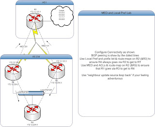
BGP Lab

Visio of a lab for practising route-maps and BGP:


Answers tomorrow !

Tuesday 2 June 2009

Custom Queueing Notes

Ratio = Bandwidth % / Avg Packet Size

Normalized = Ratio/ Lowest Ratio

Byte count = Ratio * Avg Packet Size


E.g.
HTTP
B=50%
Avg.Packet=746
Ratio=0.067
N=2
Byte Count=1492

Using Rate-Limit for traffic shapping on cisco routers.

Hi again,

This post starts like a song "..I was working in the lab late one night" and I was playing around with cisco queueing and traffic shaping and whilst working on something for a client I worked out something that maybe be obvious for most but I have never really seen it in any forums/cisco documentation.

Anyway here is the visio of the scenario:
Here is how I did it.

1) Define the ACLs (These are used later for the Class-maps)
-Pings
access-list 110 permit icmp 10.10.0.0 0.0.0.255 any
-Voip
access-list 120 permit ip 10.10.0.0 0.0.0.255 host 192.168.0.5
-DNS
access-list 130 permit tcp 10.10.0.0 0.0.0.255 any eq domain
-Http
access-list 140 permit tcp 10.10.0.0 0.0.0.255 any eq www
-Bulk traffic
access-list 160 permit ip host 192.168.0.3 any

2) Define the class-maps:

class-map match-all VOIP
match access-group 110
match access-group 120
class-map match-all PING
match access-group 110
class-map match-all HTTP
match access-group 140
class-map match-all DNS
match access-group 130

3) Create 2 policy maps. This is because you can only really control outgoing bandwidth therefore you control WAN upstream on the WAN interface
But you control WAN downstream on the LAN interface.

*****************************************
policy-map WAN_OUT
class PING
bandwidth 1024
class VOIP
priority 1024
class DNS
bandwidth 1024
class HTTP
bandwidth 4096
class class-default
fair-queue

*****************************************
policy-map LAN_OUT
class PING
bandwidth 1024
class VOIP
priority 1024
class DNS
bandwidth 1024
class HTTP
bandwidth 4096
class class-default
fair-queue
*****************************************

Then I decided to cap all downstream traffic from 192.168.0.3 to about 256KB/s
This command make sure that when a user downloads a file it can never exceed this amount
(even when not congested)
interface FastEthernet0/1
..
rate-limit output access-group 160 2000000 1000000 1000000 conform-action continue exceed-action drop
..

Notice once again at this command is applied to the LAN interface on the output.


Once finished I used http://www.testyourvoip.com to test the quality whilst user 10.10.0.3 was downloading from the internet, grabing files over FTP & SMB from 192.168.0.3.

...and it worked! scored about 4.5 where as before shaping I had a score of about 3-ish


This isnt perfect, but it was just designed to show that you dont use the input queue on the wan interface to control your downloading you use the output queue on your lan interface.


Hope this helps some people out there.