Showing posts with label tunnel. Show all posts

Saturday, 13 November 2010

Vyatta to Cisco - Tunneling from ASA to Vyatta Using VMware and GNS

Its been a while since my last article/lab apologies for that, hopefully I will get back to my once a week schedule (fingers crossed)

So that lab today is for connecting a Vyatta router to a Cisco ASA/PIX and creating a Lan to Lan Tunnel with some one to one src/dst NAT thrown in for good measure :)

Here is the lab:


Here is the proof that is works:

Vyatta to Cisco - Tunneling from ASA to Vyatta Using VMware and GNS from Roggy on Vimeo.


Vyatta config:

interfaces {
ethernet eth0 {
address 10.0.19.1/24
address 10.0.19.10/24
duplex auto
hw-id 00:0c:29:5d:91:c6
smp_affinity auto
speed auto
}
ethernet eth1 {
address 192.168.10.1/24
duplex auto
hw-id 00:0c:29:5d:91:d0
smp_affinity auto
speed auto
}
ethernet eth2 {
duplex auto
hw-id 00:0c:29:5d:91:da
smp_affinity auto
speed auto
}
loopback lo {
}
}
protocols {
static {
route 0.0.0.0/0 {
next-hop 10.0.19.9 {
}
}
}
}
service {
nat {
rule 5 {
destination {
address 10.20.0.0/24
}
exclude
outbound-interface eth0
source {
address 192.168.10.0/24
}
type masquerade
}
rule 100 {
outbound-interface eth0
outside-address {
address 10.0.19.10
}
source {
address 192.168.10.10
}
type source
}
rule 110 {
destination {
address 10.0.19.10
}
inbound-interface eth0
inside-address {
address 192.168.10.10
}
protocol tcp
type destination
}
rule 900 {
outbound-interface eth0
source {
address 192.168.10.0/24
}
type masquerade
}
}
ssh {
allow-root
port 22
protocol-version v2
}
}
system {
host-name R1
login {
user vyatta {
authentication {
encrypted-password $1$Oxg1L7oM$v4Vi.4pW3Ai/fPFIzpDzC0
}
level admin
}
}
ntp-server 0.vyatta.pool.ntp.org
package {
auto-sync 1
repository community {
components main
distribution stable
password ""
url http://packages.vyatta.com/vyatta
username ""
}
}
syslog {
global {
facility all {
level notice
}
facility protocols {
level debug
}
}
}
time-zone GMT
}
vpn {
ipsec {
esp-group ESP-1W {
compression disable
lifetime 3600
mode tunnel
pfs disable
proposal 1 {
encryption 3des
hash sha1
}
}
ike-group IKE-1W {
lifetime 86400
proposal 1 {
dh-group 2
encryption 3des
hash sha1
}
}
ipsec-interfaces {
interface eth0
}
nat-traversal enable
site-to-site {
peer 10.0.29.2 {
authentication {
mode pre-shared-secret
pre-shared-secret letmein
}
ike-group IKE-1W
local-ip 10.0.19.1
tunnel 1 {
allow-nat-networks disable
allow-public-networks disable
esp-group ESP-1W
local-subnet 192.168.10.0/24
remote-subnet 10.20.0.0/24
}
}
}
}
}


/* Warning: Do not remove the following line. */
/* === vyatta-config-version: "webgui@1:dhcp-server@4:conntrack-sync@1:firewall@3:qos@1:webproxy@1:vrrp@1:nat@3:ipsec@2:wanloadbalance@2:cluster@1:system@3:quagga@2:dhcp-relay@1" === */


Pix Config:

!
PIX Version 8.0(2)
!
hostname FW1
enable password 8Ry2YjIyt7RRXU24 encrypted
names
!
interface Ethernet0
nameif outside
security-level 0
ip address 10.0.29.2 255.255.255.0
!
interface Ethernet1
nameif inside
security-level 100
ip address 10.20.0.1 255.255.255.0
!
interface Ethernet2
shutdown
no nameif
no security-level
no ip address
!
interface Ethernet3
shutdown
no nameif
no security-level
no ip address
!
interface Ethernet4
shutdown
no nameif
no security-level
no ip address
!
passwd 2KFQnbNIdI.2KYOU encrypted
ftp mode passive
access-list icmp extended permit icmp any any
access-list NO-NAT extended permit ip 10.20.0.0 255.255.255.0 192.168.10.0 255.255.255.0
access-list IPSEC-TUN extended permit ip 10.20.0.0 255.255.255.0 192.168.10.0 255.255.255.0
pager lines 24
mtu outside 1500
mtu inside 1500
no failover
icmp unreachable rate-limit 1 burst-size 1
no asdm history enable
arp timeout 14400
global (outside) 1 interface
nat (inside) 0 access-list NO-NAT
nat (inside) 1 0.0.0.0 0.0.0.0
access-group icmp in interface outside
access-group icmp out interface outside
access-group icmp in interface inside
access-group icmp out interface inside
route outside 0.0.0.0 0.0.0.0 10.0.29.9 1
timeout xlate 3:00:00
timeout conn 1:00:00 half-closed 0:10:00 udp 0:02:00 icmp 0:00:02
timeout sunrpc 0:10:00 h323 0:05:00 h225 1:00:00 mgcp 0:05:00 mgcp-pat 0:05:00
timeout sip 0:30:00 sip_media 0:02:00 sip-invite 0:03:00 sip-disconnect 0:02:00
timeout uauth 0:05:00 absolute
dynamic-access-policy-record DfltAccessPolicy
no snmp-server location
no snmp-server contact
snmp-server enable traps snmp authentication linkup linkdown coldstart
crypto ipsec transform-set FW1-TRANSFORM esp-3des esp-sha-hmac
crypto map FW1 10 match address IPSEC-TUN
crypto map FW1 10 set peer 10.0.19.1
crypto map FW1 10 set transform-set FW1-TRANSFORM
crypto map FW1 interface outside
crypto isakmp identity address
crypto isakmp enable outside
crypto isakmp policy 100
authentication pre-share
encryption 3des
hash sha
group 2
lifetime 86400
no crypto isakmp nat-traversal
telnet timeout 5
ssh timeout 5
console timeout 0
threat-detection basic-threat
threat-detection statistics access-list
!
!
tunnel-group 10.0.19.1 type ipsec-l2l
tunnel-group 10.0.19.1 ipsec-attributes
pre-shared-key letmein
prompt hostname context


Enjoy!
Wednesday, 26 August 2009

DMVPN - How to

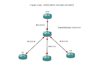
After seeing a few requests for this, I thought it would be good to do a "Dynamic Multipoint Virtual Private Network".

Which is a nice TLA for Multipoint GRE(Tunnel), NHRP(Next Hop Routing Protocol) and IPSEC.

So here is the lab:


Very boring compared to the MPLS L2 lab however there are some important techs to get used to.

For the purposes of the lab, R1 is not under our control.

Therefore all the spoke routers have a default route to the R1 and that is it.
It is up to the DMVPN to fill in the gaps.

Here is R10 which is the HQ or "Hub" router.

interface Tunnel0
!All the tunnels have to be in the same subnet
ip address 10.0.234.10 255.255.255.0
no ip redirects
ip mtu 1400
!Dynamically map to the spokes
ip nhrp map multicast dynamic
!Network-id has to be the same on all routers
ip nhrp network-id 1
ip nhrp holdtime 450
ip tcp adjust-mss 1360
!This is needed as OSPF auto-configs a "tunnel int" as point-to-point which is wrong !here
ip ospf network point-to-multipoint
!Exit interface
tunnel source FastEthernet1/0
!Tunnel mode
tunnel mode gre multipoint


R2

interface Tunnel0
ip address 10.0.234.2 255.255.255.0
no ip redirects
ip mtu 1400
ip nhrp map multicast 10.0.110.10
ip nhrp map 10.0.234.10 10.0.110.10
ip nhrp network-id 1
ip nhrp holdtime 450
ip nhrp nhs 10.0.234.10
ip tcp adjust-mss 1360
ip ospf network point-to-multipoint
tunnel source FastEthernet1/0
tunnel mode gre multipoint


R3

!
interface Tunnel0
ip address 10.0.234.3 255.255.255.0
no ip redirects
ip mtu 1400
ip nhrp map multicast 10.0.110.10
ip nhrp map 10.0.234.10 10.0.110.10
ip nhrp network-id 1
ip nhrp holdtime 450
ip nhrp nhs 10.0.234.10
ip tcp adjust-mss 1360
ip ospf network point-to-multipoint
tunnel source FastEthernet1/0
tunnel mode gre multipoint


R4

interface Tunnel0
ip address 10.0.234.4 255.255.255.0
no ip redirects
ip mtu 1400
ip nhrp map multicast 10.0.234.10
ip nhrp map 10.0.234.10 10.0.110.10
ip nhrp network-id 1
ip nhrp holdtime 450
ip nhrp nhs 10.0.234.10
ip tcp adjust-mss 1360
ip ospf network point-to-multipoint
tunnel source FastEthernet1/0
tunnel mode gre multipoint


That should be the tunnel up. At this point you can test the tunnel by ping the Hub tunnel address 10.0.234.10 from each of the spokes.

Now encryption:
R10

crypto isakmp policy 100
encr aes
authentication pre-share
group 2
crypto isakmp key letmein address 0.0.0.0 0.0.0.0
!
!
crypto ipsec transform-set TUN-TRANSFORM esp-aes esp-sha-hmac
!
crypto ipsec profile TUN-PROFILE
set transform-set TUN-TRANSFORM


Then applied to the Tunnel inteface:

interface Tunnel0
ip address 10.0.234.10 255.255.255.0
no ip redirects
ip mtu 1400
ip nhrp map multicast dynamic
ip nhrp network-id 1
ip nhrp holdtime 450
ip tcp adjust-mss 1360
ip ospf network point-to-multipoint
tunnel source FastEthernet1/0
tunnel mode gre multipoint
tunnel protection ipsec profile TUN-PROFILE
!


then the same for R2,R3,R4:

crypto isakmp policy 100
encr aes
authentication pre-share
group 2
crypto isakmp key letmein address 0.0.0.0 0.0.0.0
!
!
crypto ipsec transform-set TUN-TRANSFORM esp-aes esp-sha-hmac
!
crypto ipsec profile TUN-PROFILE
set transform-set TUN-TRANSFORM
!


~Under the Tunnel0 interface:

!
tunnel protection ipsec profile TUN-PROFILE
!


This is identicial for each spoke.

Then an example OSPF config on R2:

!
router ospf 1
router-id 2.2.2.2
log-adjacency-changes
network 2.2.2.2 0.0.0.0 area 0
network 10.0.234.0 0.0.0.255 area 0
network 192.168.2.0 0.0.0.255 area 2
!


Done!

Friday, 14 August 2009

Unequal Traffic Sharing with OSPF

Another day another lab :)

Now typically when you say to someone "hi i'm doing unequal traffic sharing with OSPF"
they will often say "no no you fool, thats not possible EIGRP is the only one to do unequal traffic"....but they would be wrong.

Using MPLS OSPF-Traffic Engineering you can indeed do Unequal Traffic Sharing.

And here is how:


As you can see this follows on directly from here


The only changes are to R2 and R5.


So R2:

!
interface Tunnel2
ip unnumbered Loopback1
mpls traffic-eng tunnels
tunnel destination 50.50.50.50
tunnel mode mpls traffic-eng
tunnel mpls traffic-eng autoroute announce
tunnel mpls traffic-eng priority 2 2
tunnel mpls traffic-eng bandwidth 512
tunnel mpls traffic-eng path-option 1 explicit name R2-R4-R5
no routing dynamic
!


and R5


interface Tunnel2
ip unnumbered Loopback1
mpls traffic-eng tunnels
tunnel destination 20.20.20.20
tunnel mode mpls traffic-eng
tunnel mpls traffic-eng autoroute announce
tunnel mpls traffic-eng priority 2 2
tunnel mpls traffic-eng bandwidth 512
tunnel mpls traffic-eng path-option 1 explicit name R5-R4-R2
no routing dynamic
!


Notice the command:
tunnel mpls traffic-eng bandwidth 512

The ensures that packets are sent in the ratio 2:1 down the two tunnels (Tunnel 1 and Tunnel 2)

Now to prove it:

R2#sh ip route 50.50.50.50
Routing entry for 50.50.50.50/32
Known via "ospf 1", distance 110, metric 3, type intra area
Last update from 50.50.50.50 on Tunnel2, 00:20:05 ago
Routing Descriptor Blocks:
* 50.50.50.50, from 5.5.5.5, 00:20:05 ago, via Tunnel2
Route metric is 3, traffic share count is 2
50.50.50.50, from 5.5.5.5, 00:20:05 ago, via Tunnel1
Route metric is 3, traffic share count is 1


and from R5

R5#sh ip route 20.20.20.20
Routing entry for 20.20.20.20/32
Known via "ospf 1", distance 110, metric 3, type intra area
Last update from 20.20.20.20 on Tunnel2, 00:20:57 ago
Routing Descriptor Blocks:
* 20.20.20.20, from 2.2.2.2, 00:20:57 ago, via Tunnel1
Route metric is 3, traffic share count is 1
20.20.20.20, from 2.2.2.2, 00:20:57 ago, via Tunnel2
Route metric is 3, traffic share count is 2


Looks good but what about debugs?
From R5 to R2:

R5#trace 20.20.20.20

Type escape sequence to abort.
Tracing the route to 20.20.20.20

1 10.0.35.3 [MPLS: Label 25 Exp 0] 48 msec
10.0.45.4 [MPLS: Label 25 Exp 0] 44 msec 8 msec
2 10.0.23.2 32 msec
10.0.24.2 36 msec *


and debugs from R4 and R3:
R4

R4#
*Aug 14 13:50:04.199: MPLS turbo: Fa1/1: rx: Len 60 Stack {25 0 1} - ipv4 data
*Aug 14 13:50:04.219: MPLS turbo: Fa1/0: rx: Len 186 Stack {17 6 253} - ipv4 data
*Aug 14 13:50:04.227: MPLS turbo: Fa1/1: rx: Len 60 Stack {25 0 1} - ipv4 data
*Aug 14 13:50:04.231: MPLS turbo: Fa1/0: rx: Len 186 Stack {17 6 253} - ipv4 data
*Aug 14 13:50:04.271: MPLS turbo: Fa1/1: rx: Len 60 Stack {25 0 2} - ipv4 data
*Aug 14 13:50:04.295: MPLS turbo: Fa1/0: rx: Len 74 Stack {17 6 255} - ipv4 data
*Aug 14 13:50:04.311: MPLS turbo: Fa1/1: rx: Len 60 Stack {25 0 2} - ipv4 data


and R3:

R3#
*Aug 14 13:50:04.035: MPLS turbo: Fa1/1: rx: Len 60 Stack {25 0 1} - ipv4 data
*Aug 14 13:50:04.051: MPLS turbo: Fa1/0: rx: Len 186 Stack {17 6 253} - ipv4 data
*Aug 14 13:50:04.127: MPLS turbo: Fa1/1: rx: Len 60 Stack {25 0 2} - ipv4 data
*Aug 14 13:50:04.159: MPLS turbo: Fa1/0: rx: Len 74 Stack {17 6 255} - ipv4 data


A ratio of 7:4..pretty good! :)

Wednesday, 12 August 2009

My First MPLS blog

I have a feeling ill be doing a few of these, MPLS is such a huge topic that simply doing a few labs does not seem to do it justice, however its better than doing none at all!

After playing around with my real lab a little I decided to virtualise this one, not to be confused with a router simulator, GNS is a great tool for knocking up a lab and playing around with ideas.

In light of that this is my latest idea:


One of the fun this that this lab was able to do was to separate the OSPF router ID from the MPLS traffic engineering router ID, this was done to hopefully better show which error/events were MPLS related those that were OSPF related and those that were a result of OSPF-TE.


I would kinda of expect you to be able to setup ip connectivity between the routers by now, after all this is basically CCIE stuff :)

Most of the below is fairly standard OSPF, however it is important to note the areas that I place the OSPF-TE router-ID and the OSPF router ID.

Setting up OSPF:
R2:

router ospf 1
router-id 2.2.2.2
log-adjacency-changes
network 2.2.2.2 0.0.0.0 area 2
network 10.0.23.0 0.0.0.255 area 0
network 10.0.24.0 0.0.0.255 area 0
network 192.168.12.0 0.0.0.255 area 12


R3

router ospf 1
router-id 3.3.3.3
log-adjacency-changes
network 3.3.3.3 0.0.0.0 area 3
network 10.0.23.0 0.0.0.255 area 0
network 10.0.35.0 0.0.0.255 area 0
!


R4

router ospf 1
router-id 4.4.4.4
log-adjacency-changes
network 4.4.4.4 0.0.0.0 area 4
network 10.0.24.0 0.0.0.255 area 0
network 10.0.45.0 0.0.0.255 area 0
!


R5

router ospf 1
router-id 5.5.5.5
log-adjacency-changes
passive-interface FastEthernet2/0
network 5.5.5.5 0.0.0.0 area 5
network 10.0.35.0 0.0.0.255 area 0
network 10.0.45.0 0.0.0.255 area 0
network 192.168.56.0 0.0.0.255 area 56
!


Ok thats ospf done.

Now MPLS, first step is to setup another loopback for MPLS and bring it into MPLS.

R2

! global
mpls traffic-eng tunnels
!
interface Loopback1
ip address 20.20.20.20 255.255.255.255
!
router ospf 1
mpls traffic-eng router-id Loopback1
mpls traffic-eng area 0

router-id 2.2.2.2
log-adjacency-changes
network 2.2.2.2 0.0.0.0 area 2
network 10.0.23.0 0.0.0.255 area 0
network 10.0.24.0 0.0.0.255 area 0
network 20.20.20.20 0.0.0.0 area 0
network 192.168.12.0 0.0.0.255 area 12
!


Now we could cheat and use "mpls ldp autoconfig area 0" here to enable LDP on all the area 0 interfaces however I like to do it manually.
While we're in the interface mode we might as well configure RSVP too :)


interface FastEthernet1/1
ip address 10.0.23.2 255.255.255.0
duplex auto
speed auto
mpls traffic-eng tunnels
mpls ip

ip rsvp bandwidth 75000 75000
!
interface FastEthernet2/0
ip address 10.0.24.2 255.255.255.0
duplex auto
speed auto
mpls traffic-eng tunnels
mpls ip

ip rsvp bandwidth 75000 75000
!


R3

mpls traffic-eng tunnels
interface Loopback1
ip address 30.30.30.30 255.255.255.255
!
interface FastEthernet1/0
ip address 10.0.23.3 255.255.255.0
duplex auto
speed auto
mpls traffic-eng tunnels
mpls ip
ip rsvp bandwidth 75000 75000
!
interface FastEthernet1/1
ip address 10.0.35.3 255.255.255.0
duplex auto
speed auto
mpls traffic-eng tunnels
mpls ip
ip rsvp bandwidth 75000 75000
!
router ospf 1
mpls traffic-eng router-id Loopback1
mpls traffic-eng area 0
router-id 3.3.3.3
log-adjacency-changes
network 3.3.3.3 0.0.0.0 area 3
network 10.0.23.0 0.0.0.255 area 0
network 10.0.35.0 0.0.0.255 area 0
network 30.30.30.30 0.0.0.0 area 0
!


R4
!
mpls traffic-eng tunnels
!
!
interface Loopback1
ip address 40.40.40.40 255.255.255.255
!
interface FastEthernet1/0
ip address 10.0.24.4 255.255.255.0
duplex auto
speed auto
mpls traffic-eng tunnels
mpls ip
ip rsvp bandwidth 75000 75000
!
interface FastEthernet1/1
ip address 10.0.45.4 255.255.255.0
duplex auto
speed auto
mpls traffic-eng tunnels
mpls ip
ip rsvp bandwidth 75000 75000
!
router ospf 1
mpls traffic-eng router-id Loopback1
mpls traffic-eng area 0
router-id 4.4.4.4
log-adjacency-changes
network 4.4.4.4 0.0.0.0 area 4
network 10.0.24.0 0.0.0.255 area 0
network 10.0.45.0 0.0.0.255 area 0
network 40.40.40.40 0.0.0.0 area 0
!


R5
mpls traffic-eng tunnels
!
interface Loopback1
ip address 50.50.50.50 255.255.255.255
!
!
interface FastEthernet1/0
ip address 10.0.35.5 255.255.255.0
duplex auto
speed auto
mpls traffic-eng tunnels
mpls ip
ip rsvp bandwidth 75000 75000
!
interface FastEthernet1/1
ip address 10.0.45.5 255.255.255.0
duplex auto
speed auto
mpls traffic-eng tunnels
mpls ip
ip rsvp bandwidth 75000 75000
!
!
router ospf 1
mpls traffic-eng router-id Loopback1
mpls traffic-eng area 0
router-id 5.5.5.5
log-adjacency-changes
passive-interface FastEthernet2/0
network 5.5.5.5 0.0.0.0 area 5
network 10.0.35.0 0.0.0.255 area 0
network 10.0.45.0 0.0.0.255 area 0
network 50.50.50.50 0.0.0.0 area 0
network 192.168.56.0 0.0.0.255 area 56
!


Now the actual Tunnels!
As they are uni-directional we need one from R2-R5 and another from R5-R2

R2-R5
interface Tunnel1
ip unnumbered Loopback1
mpls traffic-eng tunnels
tunnel destination 50.50.50.50
tunnel mode mpls traffic-eng
tunnel mpls traffic-eng autoroute announce
tunnel mpls traffic-eng priority 1 1
tunnel mpls traffic-eng bandwidth 256
tunnel mpls traffic-eng path-option 1 explicit name R2-R3-R5
!
ip explicit-path name R2-R3-R5 enable
next-address 10.0.23.3
next-address 10.0.35.5
!

and R5-R2:
!
ip explicit-path name R5-R3-R2 enable
next-address 10.0.35.3
next-address 10.0.23.2
!

Proving it works!......


R6#ping 192.168.12.1 repeat 2

Type escape sequence to abort.
Sending 2, 100-byte ICMP Echos to 192.168.12.1, timeout is 2 seconds:
!!
Success rate is 100 percent (2/2), round-trip min/avg/max = 44/48/52 ms


Results of an "debug mpls packet" from R3:

R3#
*Aug 12 20:23:59.407: MPLS turbo: Fa1/1: rx: Len 118 Stack {23 0 254} - ipv4 data
*Aug 12 20:23:59.427: MPLS turbo: Fa1/0: rx: Len 118 Stack {22 0 254} - ipv4 data
*Aug 12 20:23:59.459: MPLS turbo: Fa1/1: rx: Len 118 Stack {23 0 254} - ipv4 data
*Aug 12 20:23:59.491: MPLS turbo: Fa1/0: rx: Len 118 Stack {22 0 254} - ipv4 data


Note all 4 packets using the same route and all MPLS switched.
..and one final test:


R6#trace 192.168.12.1

Type escape sequence to abort.
Tracing the route to 192.168.12.1

1 192.168.56.5 28 msec 16 msec 4 msec
2 10.0.35.3 [MPLS: Label 23 Exp 0] 28 msec 12 msec 12 msec
3 10.0.23.2 28 msec 32 msec 12 msec
4 192.168.12.1 32 msec


Done!

Wednesday, 5 August 2009

IPSec Tunnel..with a difference.

Well although it looks like July was quiet..it wasnt :)

Got some new kit in the lab another 2610XM for more IPSec madness and a very nice 3550 EMI for some MLS shenanigans.

So i was over here: http://www.networking-forum.com/viewtopic.php?f=35&t=12877

And I thought I would blog about the problem.

Here is the Lab:


First stage was to setup static routes across the routers so here is what they looked like:
R1

ip route 172.20.1.0 255.255.255.0 192.168.4.2
ip route 172.21.1.0 255.255.255.0 192.168.4.2
ip route 192.168.1.0 255.255.255.0 192.168.4.2
ip route 192.168.3.0 255.255.255.0 192.168.4.2

Core

ip route 172.16.1.0 255.255.255.0 192.168.4.1
ip route 172.17.1.0 255.255.255.0 192.168.4.1
ip route 172.20.1.0 255.255.255.0 192.168.1.2
ip route 172.21.1.0 255.255.255.0 192.168.1.2
ip route 192.168.3.0 255.255.255.0 192.168.1.2

BB1

ip route 172.16.1.0 255.255.255.0 192.168.1.1
ip route 172.17.1.0 255.255.255.0 192.168.1.1
ip route 172.20.1.0 255.255.255.0 192.168.3.2
ip route 172.21.1.0 255.255.255.0 192.168.3.2
ip route 192.168.4.0 255.255.255.0 192.168.1.1


BB2

ip route 172.16.1.0 255.255.255.0 192.168.3.1
ip route 172.17.1.0 255.255.255.0 192.168.3.1
ip route 192.168.1.0 255.255.255.0 192.168.3.1
ip route 192.168.4.0 255.255.255.0 192.168.3.1


Next step was to get up ISAKMP Policies on CORE and BB2 like this:
(same on each router)

crypto isakmp policy 100
encr 3des
authentication pre-share
group 2
crypto isakmp key letmein address 0.0.0.0 0.0.0.0


Then IPSEC transform sets:
Core:

crypto ipsec transform-set CORE_TRANSFORM esp-3des esp-sha-hmac

BB2:

crypto ipsec transform-set BB2_TRANSFORM esp-3des esp-sha-hmac


Then Crypto ACLs, now you have to be becareful with these as from what I have seen this is the number one area where people slip up ( and the PFS setting)
Rememeber it is always from perspective of which traffic you wish to be encrypted when it leaves the interface you apply the map too.


So here are the Crypto ACLs;
Core:

!This is to allow BB2 to ping 172.16.1.1 (from console)
access-list 100 permit ip host 172.16.1.1 host 192.168.3.2
!This is to allow BB2 to ping 172.17.1.1 (from console)
access-list 100 permit ip host 172.17.1.1 host 192.168.3.2
!This is to allow R1 to ping 172.20.1.1 (from console)
access-list 100 permit ip host 192.168.4.1 host 172.20.1.1
!This is to allow R1 to ping 172.21.1.1 (from console)
access-list 100 permit ip host 192.168.4.1 host 172.21.1.1
!This is to allow R1's networks to connect to BB2's Networks
access-list 100 permit ip 172.16.1.0 0.0.0.255 172.20.1.0 0.0.0.255
access-list 100 permit ip 172.16.1.0 0.0.0.255 172.21.1.0 0.0.0.255
access-list 100 permit ip 172.17.1.0 0.0.0.255 172.20.1.0 0.0.0.255
access-list 100 permit ip 172.17.1.0 0.0.0.255 172.21.1.0 0.0.0.255


BB2:

!This is to allow BB2 to ping 172.16.1.1 (from console)
access-list 100 permit ip host 192.168.3.2 host 172.16.1.1
!This is to allow BB2 to ping 172.17.1.1 (from console)
access-list 100 permit ip host 192.168.3.2 host 172.17.1.1
!This is to allow R1 to ping 172.21.1.1 (from console)
access-list 100 permit ip host 172.21.1.1 host 192.168.4.1
!This is to allow R1 to ping 172.21.1.1 (from console)
access-list 100 permit ip host 172.20.1.1 host 192.168.4.1
!This is to allow BB2's networks to connect to R1's Networks
access-list 100 permit ip 172.20.1.0 0.0.0.255 172.16.1.0 0.0.0.255
access-list 100 permit ip 172.21.1.0 0.0.0.255 172.16.1.0 0.0.0.255
access-list 100 permit ip 172.20.1.0 0.0.0.255 172.17.1.0 0.0.0.255
access-list 100 permit ip 172.21.1.0 0.0.0.255 172.17.1.0 0.0.0.255


Then bring it all together with a Crypto Map:
Core:

crypto map R12BB2 10 ipsec-isakmp
set peer 192.168.3.2
set transform-set CORE_TRANSFORM
match address 100


BB2:

crypto map BB22R1 10 ipsec-isakmp
set peer 192.168.1.1
set transform-set BB2_TRANSFORM
match address 100


Then apply the Crypto maps under the interfaces:
Core:

crypto map R12BB2

BB2

crypto map BB22R1