Monday, 31 August 2009

PIX/ASA Site-to-Site (L2L) VPN with DMZ-Howto

Ok this the how to for this lab: here


So lets start from the Remote Office "FW2"

First we need to set up ASA:
FW2

!
interface Ethernet0
nameif Outside
security-level 0
ip address 10.0.2.2 255.255.255.0
!
interface Ethernet1
nameif DMZ
security-level 50
ip address 192.168.20.2 255.255.255.0
!
interface Ethernet2
nameif Inside
security-level 100
ip address 192.168.2.2 255.255.255.0
!


Now NAT:

nat (Inside) 1 0.0.0.0 0.0.0.0
!Most people might like global (Outside) 1 interface instead
global (Outside) 1 10.0.2.50


Notice the "1" above, that ties the entrys together essentially saying on "these people on the inside (0.0.0.0) (everyone) are translated to this address "10.0.2.50" on the outside.

Now for testing we want to allow ICMP to the firewall

access-list WAN_IN extended permit icmp any any


Then assign it to an interface:

access-group WAN_IN in interface Outside


Add a default route:

route Outside 0.0.0.0 0.0.0.0 10.0.2.10 1


Ok we now have "internet access"

Next we need to setup the web server(192.168.20.100) with 1-to-1 nat:

nat (DMZ) 2 0.0.0.0 0.0.0.0
global (Outside) 2 10.0.2.100
static (DMZ,Outside) 10.0.2.100 192.168.20.100 netmask 255.255.255.255


Now NAT is setup, we actually need to let something through:

access-list WAN_IN extended permit tcp any host 10.0.2.100 eq telnet
access-list WAN_IN extended permit tcp any host 10.0.2.100 eq http


ok that was easy :)

Now for the HQ site:
First setup the pix:
FW1

interface Ethernet0
nameif outside
security-level 0
ip address 10.0.1.1 255.255.255.0
!
interface Ethernet1
nameif inside
security-level 100
ip address 192.168.1.1 255.255.255.0
!


Now NAT for FW1:

nat (inside) 1 0.0.0.0 0.0.0.0
global (outside) 1 interface


Ok now the tough part, actually this should be the easy part as we have done IPSec to death so far on the blog, and although the syntax looks different, actually typing it is pretty much the same as IOS.

One FW2
Set up an ISAKMP Policy:

crypto isakmp policy 100
authentication pre-share
encryption aes
hash sha
group 2
lifetime 86400


Then a Transform Set:

crypto ipsec transform-set FW1-TRANSFORM esp-aes esp-sha-hmac


Specify the traffic we dont want NAT applied too:

access-list NO-NAT extended permit ip 192.168.1.0 255.255.255.0 192.168.2.0 255.255.255.0
nat (inside) 0 access-list NO-NAT


The 0 indicates "dont NAT this"

Bring it all together with a crypto map:

access-list IPSEC-TUN extended permit ip 192.168.1.0 255.255.255.0 192.168.2.0 255.255.255.0
crypto map FW1 10 match address IPSEC-TUN
crypto map FW1 10 set peer 10.0.2.2
crypto map FW1 10 set transform-set FW1-TRANSFORM


Enable it on an interface:

crypto map FW1 interface outside


Add a tunnel group (if it is not already done for you)

tunnel-group 10.0.2.2 type ipsec-l2l
tunnel-group 10.0.2.2 ipsec-attributes
pre-shared-key letmein


Actually allow ISAKMP to connect to the outside interface:

crypto isakmp enable outside


Then the reverse/same on FW1:

access-list IPSEC-TUN extended permit ip 192.168.1.0 255.255.255.0 192.168.2.0 255.255.255.0
access-list NO-NAT extended permit ip 192.168.1.0 255.255.255.0 192.168.2.0 255.255.255.0
nat (inside) 0 access-list NO-NAT
crypto ipsec transform-set FW1-TRANSFORM esp-aes esp-sha-hmac
crypto map FW1 10 match address IPSEC-TUN
crypto map FW1 10 set peer 10.0.2.2
crypto map FW1 10 set transform-set FW1-TRANSFORM
crypto map FW1 interface outside
crypto isakmp enable outside
crypto isakmp policy 100
authentication pre-share
encryption aes
hash sha
group 2
lifetime 86400
tunnel-group 10.0.2.2 type ipsec-l2l
tunnel-group 10.0.2.2 ipsec-attributes
pre-shared-key *
prompt hostname context


Done!

Pix/ASA does alot for you in l2l ipsec vpns..and they still dont call it "easy vpn" :)
Thursday, 27 August 2009

PIX/ASA Site-to-Site (L2L) VPN with DMZ

Something a little different PIX!

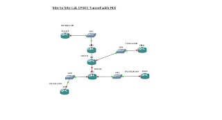
Heres the lab I've done and I will up the configs tomorrow.

First in GNS:


Then Opendraw:

L2TPv3 over IPSec with VLANS-How to

This is the practical of this lab: here

The idea of this lab is to bridge the local lan across the internet or another network you do not control to another lan, matching lan.

In this example we have 3 sites. Site 1 (which is the head office) with a server for each site (server 2 and server 3). L2TPv3 works by taking the frame recieved on its lan interface wraps it up int L2TP goodness and off it goes.

Again what makes this cool is that the workstations (PC2 and PC3) have no idea that the Servers are at another site.

Ok now your up to speed...:


First each router has a default route to R0
R2:

ip route 0.0.0.0 0.0.0.0 10.0.20.10

R3:

ip route 0.0.0.0 0.0.0.0 10.0.30.10


R1:

ip route 0.0.0.0 0.0.0.0 10.0.10.10


Ok now to the Layer 2 setup, as GNS can not do Switches (well properly anyway) you have to use a Cisco 3725 with a 16 port Ethernet Switch card.

So firstly the trunks on R1, R2 and R3

R1

!
interface FastEthernet1/1.200
encapsulation dot1Q 200
!
interface FastEthernet1/1.300
encapsulation dot1Q 300

!

R2

!
interface FastEthernet1/1.200
encapsulation dot1Q 200
!

R3

!
interface FastEthernet1/1.300
encapsulation dot1Q 300
!


Then setting up the switch:
Switch1

interface FastEthernet1/1
switchport mode trunk
!
interface FastEthernet1/2
switchport access vlan 200
!
interface FastEthernet1/3
switchport access vlan 300
!


Switch2

!
interface FastEthernet1/1
switchport mode trunk
!
interface FastEthernet1/2
switchport access vlan 200
!


Switch3

!
interface FastEthernet1/1
switchport mode trunk
!
interface FastEthernet1/2
switchport access vlan 300
!


I'll leave the setting up of the IP addresses to you :)

Ok now to the fun stuff the L2TPv3 setup:

R1

l2tp-class l2tp-defaults
retransmit initial retries 30
cookie size 8
!
!
pseudowire-class VLANS
encapsulation l2tpv3
protocol none
ip local interface FastEthernet1/0
!


R2

l2tp-class l2tp-defaults
retransmit initial retries 30
cookie size 8
!
!
pseudowire-class VLAN200
encapsulation l2tpv3
protocol none
ip local interface FastEthernet1/0
!


R3

l2tp-class l2tp-defaults
retransmit initial retries 30
cookie size 8
!
pseudowire-class VLAN300
encapsulation l2tpv3
protocol none
ip local interface FastEthernet1/0
!


Now part two of the setup, which is the actual pseudeowire!
R1

!
interface FastEthernet1/1.200
encapsulation dot1Q 200
! The vc 200 here is not used...call it anything you like!
xconnect 10.0.20.2 200 encapsulation l2tpv3 manual pw-class VLANS
! This id is important 102 and 202 must be swaped on the other end
l2tp id 102 202
! "remote" is data sent
! "local" is data expected to be recieved.
! Therefore 221200 is Router 2 2 Router 1 VLAN 200 (R22R1VLAN200)
! Just makes it easier for you, but you can do any number as long as
! it is flipped
l2tp cookie local 4 221200
l2tp cookie remote 4 122200
l2tp hello l2tp-defaults
!
interface FastEthernet1/1.300
encapsulation dot1Q 300
xconnect 10.0.30.3 300 encapsulation l2tpv3 manual pw-class VLANS
l2tp id 103 303
l2tp cookie local 4 321300
l2tp cookie remote 4 123300
l2tp hello l2tp-default
s
!


Then the spokes:
R2

!
interface FastEthernet1/1.200
encapsulation dot1Q 200
ip virtual-reassembly
xconnect 10.0.10.1 200 encapsulation l2tpv3 manual pw-class VLAN200
l2tp id 202 102
l2tp cookie local 4 122200
l2tp cookie remote 4 221200
l2tp hello l2tp-defaults
!


R3

interface FastEthernet1/1.300
encapsulation dot1Q 300
ip virtual-reassembly
xconnect 10.0.10.1 300 encapsulation l2tpv3 manual pw-class VLAN300
l2tp id 303 103
l2tp cookie local 4 123300
l2tp cookie remote 4 321300
l2tp hello l2tp-defaults
!


You can now test that it works, however at the moment it is all unencrypted!

Therefore encryption;
R1

!
crypto isakmp policy 100
encr 3des
authentication pre-share
group 2
crypto isakmp key letmein address 0.0.0.0 0.0.0.0
!
!
crypto ipsec transform-set R1-TRANSFORM esp-3des esp-sha-hmac
!
crypto map R12R2R3 100 ipsec-isakmp
set peer 10.0.30.3
set transform-set R1-TRANSFORM
match address 110
crypto map R12R2R3 200 ipsec-isakmp
set peer 10.0.20.2
set transform-set R1-TRANSFORM
match address 100
!
access-list 100 permit ip host 10.0.10.1 host 10.0.20.2
access-list 110 permit ip host 10.0.10.1 host 10.0.30.3
!
!
interface FastEthernet1/0
ip address 10.0.10.1 255.255.255.0
ip virtual-reassembly
duplex auto
speed auto
crypto map R12R2R3
!


R2

!
crypto isakmp policy 100
encr 3des
authentication pre-share
group 2
crypto isakmp key letmein address 0.0.0.0 0.0.0.0
!
!
crypto ipsec transform-set R2-TRANSFORM esp-3des esp-sha-hmac
!
crypto map R22R1 100 ipsec-isakmp
set peer 10.0.10.1
set transform-set R2-TRANSFORM
match address 100
!
!
access-list 100 permit ip host 10.0.20.2 host 10.0.10.1
!
!
interface FastEthernet1/0
ip address 10.0.20.2 255.255.255.0
ip virtual-reassembly
duplex auto
speed auto
crypto map R22R1
!


R3

!
crypto isakmp policy 100
encr 3des
authentication pre-share
group 2
crypto isakmp key letmein address 0.0.0.0 0.0.0.0
!
!
crypto ipsec transform-set R3-TRANSFORM esp-3des esp-sha-hmac
!
crypto map R32R1 100 ipsec-isakmp
set peer 10.0.10.1
set transform-set R3-TRANSFORM
match address 100
!
access-list 100 permit ip host 10.0.30.3 host 10.0.10.1
!
!
interface FastEthernet1/0
ip address 10.0.30.3 255.255.255.0
ip virtual-reassembly
duplex auto
speed auto
crypto map R32R1
!


Bit of a sledgehammer approach to encryption as everything will be wrapped up in ESP, however if you wish to do this for just L2TP then an ACL for UDP 1701 will do the job nicely.

Done!

Wednesday, 26 August 2009

L2TPv3 over IPSec with VLANS

Here is the Lab:
From GNS:


Then from Opendraw:


Not sure which I prefer yet, the Cisco-ish one is pretty but GNS is functional..hmm

DMVPN - How to

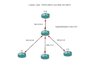
After seeing a few requests for this, I thought it would be good to do a "Dynamic Multipoint Virtual Private Network".

Which is a nice TLA for Multipoint GRE(Tunnel), NHRP(Next Hop Routing Protocol) and IPSEC.

So here is the lab:


Very boring compared to the MPLS L2 lab however there are some important techs to get used to.

For the purposes of the lab, R1 is not under our control.

Therefore all the spoke routers have a default route to the R1 and that is it.
It is up to the DMVPN to fill in the gaps.

Here is R10 which is the HQ or "Hub" router.

interface Tunnel0
!All the tunnels have to be in the same subnet
ip address 10.0.234.10 255.255.255.0
no ip redirects
ip mtu 1400
!Dynamically map to the spokes
ip nhrp map multicast dynamic
!Network-id has to be the same on all routers
ip nhrp network-id 1
ip nhrp holdtime 450
ip tcp adjust-mss 1360
!This is needed as OSPF auto-configs a "tunnel int" as point-to-point which is wrong !here
ip ospf network point-to-multipoint
!Exit interface
tunnel source FastEthernet1/0
!Tunnel mode
tunnel mode gre multipoint


R2

interface Tunnel0
ip address 10.0.234.2 255.255.255.0
no ip redirects
ip mtu 1400
ip nhrp map multicast 10.0.110.10
ip nhrp map 10.0.234.10 10.0.110.10
ip nhrp network-id 1
ip nhrp holdtime 450
ip nhrp nhs 10.0.234.10
ip tcp adjust-mss 1360
ip ospf network point-to-multipoint
tunnel source FastEthernet1/0
tunnel mode gre multipoint


R3

!
interface Tunnel0
ip address 10.0.234.3 255.255.255.0
no ip redirects
ip mtu 1400
ip nhrp map multicast 10.0.110.10
ip nhrp map 10.0.234.10 10.0.110.10
ip nhrp network-id 1
ip nhrp holdtime 450
ip nhrp nhs 10.0.234.10
ip tcp adjust-mss 1360
ip ospf network point-to-multipoint
tunnel source FastEthernet1/0
tunnel mode gre multipoint


R4

interface Tunnel0
ip address 10.0.234.4 255.255.255.0
no ip redirects
ip mtu 1400
ip nhrp map multicast 10.0.234.10
ip nhrp map 10.0.234.10 10.0.110.10
ip nhrp network-id 1
ip nhrp holdtime 450
ip nhrp nhs 10.0.234.10
ip tcp adjust-mss 1360
ip ospf network point-to-multipoint
tunnel source FastEthernet1/0
tunnel mode gre multipoint


That should be the tunnel up. At this point you can test the tunnel by ping the Hub tunnel address 10.0.234.10 from each of the spokes.

Now encryption:
R10

crypto isakmp policy 100
encr aes
authentication pre-share
group 2
crypto isakmp key letmein address 0.0.0.0 0.0.0.0
!
!
crypto ipsec transform-set TUN-TRANSFORM esp-aes esp-sha-hmac
!
crypto ipsec profile TUN-PROFILE
set transform-set TUN-TRANSFORM


Then applied to the Tunnel inteface:

interface Tunnel0
ip address 10.0.234.10 255.255.255.0
no ip redirects
ip mtu 1400
ip nhrp map multicast dynamic
ip nhrp network-id 1
ip nhrp holdtime 450
ip tcp adjust-mss 1360
ip ospf network point-to-multipoint
tunnel source FastEthernet1/0
tunnel mode gre multipoint
tunnel protection ipsec profile TUN-PROFILE
!


then the same for R2,R3,R4:

crypto isakmp policy 100
encr aes
authentication pre-share
group 2
crypto isakmp key letmein address 0.0.0.0 0.0.0.0
!
!
crypto ipsec transform-set TUN-TRANSFORM esp-aes esp-sha-hmac
!
crypto ipsec profile TUN-PROFILE
set transform-set TUN-TRANSFORM
!


~Under the Tunnel0 interface:

!
tunnel protection ipsec profile TUN-PROFILE
!


This is identicial for each spoke.

Then an example OSPF config on R2:

!
router ospf 1
router-id 2.2.2.2
log-adjacency-changes
network 2.2.2.2 0.0.0.0 area 0
network 10.0.234.0 0.0.0.255 area 0
network 192.168.2.0 0.0.0.255 area 2
!


Done!

MPLS L2VPN with 2 Customers-How to

Well its been a couple of weeks since my last post, partly due to a weeks holiday in Wales:


And although I didnt live under a bridge for a week like some sort of troll, I did go walking my dog near where this picture was taken, and this church:


Anyway..enough about my holiday and on to MPLS L2VPNs.

Diagram here


First thing to say about L2VPNs is that they are sometimes called "pseudowire". This bascially means that the idea of the L2VPN be it over MPLS (or L2TPv3) is to bridge the ethernet frame arriving on the PE interface over the MPLS network to the exiting
PE router.

So from the diagram the ethernet packet arrives at R1 int f2/1 and leaves R7 int f2/0.

Once you have set up the Provider IGP which in this case is OSPF, make sure that each router has a loopback with a 32bit mask and that loopback is brought into OSPF area 0
like this for R6:

!
interface Loopback0
ip address 6.6.6.6 255.255.255.255

!

!
router ospf 1
router-id 6.6.6.6
log-adjacency-changes
network 6.6.6.6 0.0.0.0 area 0
network 10.0.36.0 0.0.0.255 area 0
network 10.0.46.0 0.0.0.255 area 0
network 10.0.56.0 0.0.0.255 area 0
network 10.0.67.0 0.0.0.255 area 0
network 10.0.68.0 0.0.0.255 area 0
!


Then each interface which you want to run MPLS on has it enabled:
(again from R6)
(obviously this will need to be done on each provider router (interface) in the MPLS network)


!
interface FastEthernet1/0
ip address 10.0.46.6 255.255.255.0
duplex auto
speed auto
mpls ip
!
interface FastEthernet1/1
ip address 10.0.36.6 255.255.255.0
duplex auto
speed auto
mpls ip
!
interface FastEthernet2/0
ip address 10.0.56.6 255.255.255.0
duplex auto
speed auto
mpls ip
!
interface FastEthernet2/1
ip address 10.0.67.6 255.255.255.0
duplex auto
speed auto
mpls ip
!
interface FastEthernet3/0
ip address 10.0.68.6 255.255.255.0
duplex auto
speed auto
mpls ip
!
interface FastEthernet3/1
no ip address
shutdown
duplex auto
speed auto
!


Once the IGP is fully functional and you can for example ping from 1.1.1.1 to 7.7.7.7
you have a LSP (Label Switched Path) you can confirm its using MPLS (LFIB) by doing a
trace 7.7.7.7 and you will see it taking the LSP.


So how do I do this L2VPN then...well its so simply once you have the provider network up:
R1

interface FastEthernet2/0
description Customer1-R11
no ip address
duplex auto
speed auto
xconnect 8.8.8.8 101 encapsulation mpls
!


8.8.8.8 is the exit router

then on 8.8.8.8 (R8)

interface FastEthernet2/0
no ip address
duplex auto
speed auto
xconnect 1.1.1.1 101 encapsulation mpls
!


1.1.1.1 being the router on the other end.
Notice that the VC "101" is identicial as this is label within a label that follows the packet within the MPLS network.


...now for the fun bit!

High Avaliablity with Psuedowire is done via the "backup" command when in the "xconnect" context.

Here is how:
(This is for the Customer 2 (R21-R22)

R2

interface FastEthernet2/0
no ip address
duplex auto
speed auto
xconnect 7.7.7.7 301 encapsulation mpls
backup peer 8.8.8.8 302
!


R1

interface FastEthernet2/1
no ip address
duplex auto
speed auto
xconnect 8.8.8.8 201 encapsulation mpls
backup peer 7.7.7.7 202
!

R7

interface FastEthernet2/0
no ip address
duplex auto
speed auto
xconnect 2.2.2.2 301 encapsulation mpls
backup peer 1.1.1.1 202
!


R8

interface FastEthernet1/1
no ip address
duplex auto
speed auto
xconnect 1.1.1.1 201 encapsulation mpls
backup peer 2.2.2.2 302
!


One thing is that interesting is that without extra configuration the PE router will not switch to the backup peer unless the LSP is detected as being dead.

As so with this amount of redundency you maybe left with the situation where
the 10.0.12.0 network is plugged into the 10.0.21.0 network which would require the customer to make a config change before service would return.

Friday, 14 August 2009

MPLS L2VPN with 2 Customers

Here is a cool lab that I will be explaining:

Bit of humour

Genius:

Unequal Traffic Sharing with OSPF

Another day another lab :)

Now typically when you say to someone "hi i'm doing unequal traffic sharing with OSPF"
they will often say "no no you fool, thats not possible EIGRP is the only one to do unequal traffic"....but they would be wrong.

Using MPLS OSPF-Traffic Engineering you can indeed do Unequal Traffic Sharing.

And here is how:


As you can see this follows on directly from here


The only changes are to R2 and R5.


So R2:

!
interface Tunnel2
ip unnumbered Loopback1
mpls traffic-eng tunnels
tunnel destination 50.50.50.50
tunnel mode mpls traffic-eng
tunnel mpls traffic-eng autoroute announce
tunnel mpls traffic-eng priority 2 2
tunnel mpls traffic-eng bandwidth 512
tunnel mpls traffic-eng path-option 1 explicit name R2-R4-R5
no routing dynamic
!


and R5


interface Tunnel2
ip unnumbered Loopback1
mpls traffic-eng tunnels
tunnel destination 20.20.20.20
tunnel mode mpls traffic-eng
tunnel mpls traffic-eng autoroute announce
tunnel mpls traffic-eng priority 2 2
tunnel mpls traffic-eng bandwidth 512
tunnel mpls traffic-eng path-option 1 explicit name R5-R4-R2
no routing dynamic
!


Notice the command:
tunnel mpls traffic-eng bandwidth 512

The ensures that packets are sent in the ratio 2:1 down the two tunnels (Tunnel 1 and Tunnel 2)

Now to prove it:

R2#sh ip route 50.50.50.50
Routing entry for 50.50.50.50/32
Known via "ospf 1", distance 110, metric 3, type intra area
Last update from 50.50.50.50 on Tunnel2, 00:20:05 ago
Routing Descriptor Blocks:
* 50.50.50.50, from 5.5.5.5, 00:20:05 ago, via Tunnel2
Route metric is 3, traffic share count is 2
50.50.50.50, from 5.5.5.5, 00:20:05 ago, via Tunnel1
Route metric is 3, traffic share count is 1


and from R5

R5#sh ip route 20.20.20.20
Routing entry for 20.20.20.20/32
Known via "ospf 1", distance 110, metric 3, type intra area
Last update from 20.20.20.20 on Tunnel2, 00:20:57 ago
Routing Descriptor Blocks:
* 20.20.20.20, from 2.2.2.2, 00:20:57 ago, via Tunnel1
Route metric is 3, traffic share count is 1
20.20.20.20, from 2.2.2.2, 00:20:57 ago, via Tunnel2
Route metric is 3, traffic share count is 2


Looks good but what about debugs?
From R5 to R2:

R5#trace 20.20.20.20

Type escape sequence to abort.
Tracing the route to 20.20.20.20

1 10.0.35.3 [MPLS: Label 25 Exp 0] 48 msec
10.0.45.4 [MPLS: Label 25 Exp 0] 44 msec 8 msec
2 10.0.23.2 32 msec
10.0.24.2 36 msec *


and debugs from R4 and R3:
R4

R4#
*Aug 14 13:50:04.199: MPLS turbo: Fa1/1: rx: Len 60 Stack {25 0 1} - ipv4 data
*Aug 14 13:50:04.219: MPLS turbo: Fa1/0: rx: Len 186 Stack {17 6 253} - ipv4 data
*Aug 14 13:50:04.227: MPLS turbo: Fa1/1: rx: Len 60 Stack {25 0 1} - ipv4 data
*Aug 14 13:50:04.231: MPLS turbo: Fa1/0: rx: Len 186 Stack {17 6 253} - ipv4 data
*Aug 14 13:50:04.271: MPLS turbo: Fa1/1: rx: Len 60 Stack {25 0 2} - ipv4 data
*Aug 14 13:50:04.295: MPLS turbo: Fa1/0: rx: Len 74 Stack {17 6 255} - ipv4 data
*Aug 14 13:50:04.311: MPLS turbo: Fa1/1: rx: Len 60 Stack {25 0 2} - ipv4 data


and R3:

R3#
*Aug 14 13:50:04.035: MPLS turbo: Fa1/1: rx: Len 60 Stack {25 0 1} - ipv4 data
*Aug 14 13:50:04.051: MPLS turbo: Fa1/0: rx: Len 186 Stack {17 6 253} - ipv4 data
*Aug 14 13:50:04.127: MPLS turbo: Fa1/1: rx: Len 60 Stack {25 0 2} - ipv4 data
*Aug 14 13:50:04.159: MPLS turbo: Fa1/0: rx: Len 74 Stack {17 6 255} - ipv4 data


A ratio of 7:4..pretty good! :)

Wednesday, 12 August 2009

My First MPLS blog

I have a feeling ill be doing a few of these, MPLS is such a huge topic that simply doing a few labs does not seem to do it justice, however its better than doing none at all!

After playing around with my real lab a little I decided to virtualise this one, not to be confused with a router simulator, GNS is a great tool for knocking up a lab and playing around with ideas.

In light of that this is my latest idea:


One of the fun this that this lab was able to do was to separate the OSPF router ID from the MPLS traffic engineering router ID, this was done to hopefully better show which error/events were MPLS related those that were OSPF related and those that were a result of OSPF-TE.


I would kinda of expect you to be able to setup ip connectivity between the routers by now, after all this is basically CCIE stuff :)

Most of the below is fairly standard OSPF, however it is important to note the areas that I place the OSPF-TE router-ID and the OSPF router ID.

Setting up OSPF:
R2:

router ospf 1
router-id 2.2.2.2
log-adjacency-changes
network 2.2.2.2 0.0.0.0 area 2
network 10.0.23.0 0.0.0.255 area 0
network 10.0.24.0 0.0.0.255 area 0
network 192.168.12.0 0.0.0.255 area 12


R3

router ospf 1
router-id 3.3.3.3
log-adjacency-changes
network 3.3.3.3 0.0.0.0 area 3
network 10.0.23.0 0.0.0.255 area 0
network 10.0.35.0 0.0.0.255 area 0
!


R4

router ospf 1
router-id 4.4.4.4
log-adjacency-changes
network 4.4.4.4 0.0.0.0 area 4
network 10.0.24.0 0.0.0.255 area 0
network 10.0.45.0 0.0.0.255 area 0
!


R5

router ospf 1
router-id 5.5.5.5
log-adjacency-changes
passive-interface FastEthernet2/0
network 5.5.5.5 0.0.0.0 area 5
network 10.0.35.0 0.0.0.255 area 0
network 10.0.45.0 0.0.0.255 area 0
network 192.168.56.0 0.0.0.255 area 56
!


Ok thats ospf done.

Now MPLS, first step is to setup another loopback for MPLS and bring it into MPLS.

R2

! global
mpls traffic-eng tunnels
!
interface Loopback1
ip address 20.20.20.20 255.255.255.255
!
router ospf 1
mpls traffic-eng router-id Loopback1
mpls traffic-eng area 0

router-id 2.2.2.2
log-adjacency-changes
network 2.2.2.2 0.0.0.0 area 2
network 10.0.23.0 0.0.0.255 area 0
network 10.0.24.0 0.0.0.255 area 0
network 20.20.20.20 0.0.0.0 area 0
network 192.168.12.0 0.0.0.255 area 12
!


Now we could cheat and use "mpls ldp autoconfig area 0" here to enable LDP on all the area 0 interfaces however I like to do it manually.
While we're in the interface mode we might as well configure RSVP too :)


interface FastEthernet1/1
ip address 10.0.23.2 255.255.255.0
duplex auto
speed auto
mpls traffic-eng tunnels
mpls ip

ip rsvp bandwidth 75000 75000
!
interface FastEthernet2/0
ip address 10.0.24.2 255.255.255.0
duplex auto
speed auto
mpls traffic-eng tunnels
mpls ip

ip rsvp bandwidth 75000 75000
!


R3

mpls traffic-eng tunnels
interface Loopback1
ip address 30.30.30.30 255.255.255.255
!
interface FastEthernet1/0
ip address 10.0.23.3 255.255.255.0
duplex auto
speed auto
mpls traffic-eng tunnels
mpls ip
ip rsvp bandwidth 75000 75000
!
interface FastEthernet1/1
ip address 10.0.35.3 255.255.255.0
duplex auto
speed auto
mpls traffic-eng tunnels
mpls ip
ip rsvp bandwidth 75000 75000
!
router ospf 1
mpls traffic-eng router-id Loopback1
mpls traffic-eng area 0
router-id 3.3.3.3
log-adjacency-changes
network 3.3.3.3 0.0.0.0 area 3
network 10.0.23.0 0.0.0.255 area 0
network 10.0.35.0 0.0.0.255 area 0
network 30.30.30.30 0.0.0.0 area 0
!


R4
!
mpls traffic-eng tunnels
!
!
interface Loopback1
ip address 40.40.40.40 255.255.255.255
!
interface FastEthernet1/0
ip address 10.0.24.4 255.255.255.0
duplex auto
speed auto
mpls traffic-eng tunnels
mpls ip
ip rsvp bandwidth 75000 75000
!
interface FastEthernet1/1
ip address 10.0.45.4 255.255.255.0
duplex auto
speed auto
mpls traffic-eng tunnels
mpls ip
ip rsvp bandwidth 75000 75000
!
router ospf 1
mpls traffic-eng router-id Loopback1
mpls traffic-eng area 0
router-id 4.4.4.4
log-adjacency-changes
network 4.4.4.4 0.0.0.0 area 4
network 10.0.24.0 0.0.0.255 area 0
network 10.0.45.0 0.0.0.255 area 0
network 40.40.40.40 0.0.0.0 area 0
!


R5
mpls traffic-eng tunnels
!
interface Loopback1
ip address 50.50.50.50 255.255.255.255
!
!
interface FastEthernet1/0
ip address 10.0.35.5 255.255.255.0
duplex auto
speed auto
mpls traffic-eng tunnels
mpls ip
ip rsvp bandwidth 75000 75000
!
interface FastEthernet1/1
ip address 10.0.45.5 255.255.255.0
duplex auto
speed auto
mpls traffic-eng tunnels
mpls ip
ip rsvp bandwidth 75000 75000
!
!
router ospf 1
mpls traffic-eng router-id Loopback1
mpls traffic-eng area 0
router-id 5.5.5.5
log-adjacency-changes
passive-interface FastEthernet2/0
network 5.5.5.5 0.0.0.0 area 5
network 10.0.35.0 0.0.0.255 area 0
network 10.0.45.0 0.0.0.255 area 0
network 50.50.50.50 0.0.0.0 area 0
network 192.168.56.0 0.0.0.255 area 56
!


Now the actual Tunnels!
As they are uni-directional we need one from R2-R5 and another from R5-R2

R2-R5
interface Tunnel1
ip unnumbered Loopback1
mpls traffic-eng tunnels
tunnel destination 50.50.50.50
tunnel mode mpls traffic-eng
tunnel mpls traffic-eng autoroute announce
tunnel mpls traffic-eng priority 1 1
tunnel mpls traffic-eng bandwidth 256
tunnel mpls traffic-eng path-option 1 explicit name R2-R3-R5
!
ip explicit-path name R2-R3-R5 enable
next-address 10.0.23.3
next-address 10.0.35.5
!

and R5-R2:
!
ip explicit-path name R5-R3-R2 enable
next-address 10.0.35.3
next-address 10.0.23.2
!

Proving it works!......


R6#ping 192.168.12.1 repeat 2

Type escape sequence to abort.
Sending 2, 100-byte ICMP Echos to 192.168.12.1, timeout is 2 seconds:
!!
Success rate is 100 percent (2/2), round-trip min/avg/max = 44/48/52 ms


Results of an "debug mpls packet" from R3:

R3#
*Aug 12 20:23:59.407: MPLS turbo: Fa1/1: rx: Len 118 Stack {23 0 254} - ipv4 data
*Aug 12 20:23:59.427: MPLS turbo: Fa1/0: rx: Len 118 Stack {22 0 254} - ipv4 data
*Aug 12 20:23:59.459: MPLS turbo: Fa1/1: rx: Len 118 Stack {23 0 254} - ipv4 data
*Aug 12 20:23:59.491: MPLS turbo: Fa1/0: rx: Len 118 Stack {22 0 254} - ipv4 data


Note all 4 packets using the same route and all MPLS switched.
..and one final test:


R6#trace 192.168.12.1

Type escape sequence to abort.
Tracing the route to 192.168.12.1

1 192.168.56.5 28 msec 16 msec 4 msec
2 10.0.35.3 [MPLS: Label 23 Exp 0] 28 msec 12 msec 12 msec
3 10.0.23.2 28 msec 32 msec 12 msec
4 192.168.12.1 32 msec


Done!

Thursday, 6 August 2009

NAT with VLANs, ACLs and PAT & Passive FTP

Another day another blog post...oh wait thats not right...doing too many blog posts this week.


Ok here is the setup for you;

You have been asked to setup two servers in a DMZ of sorts, One HTTP server and One FTP server. However they must be in two separate VLANS and the router must stop communication between them.

Here is the lab:


Start by setting up the VLAN on FA0/0:
Vlan 200:

!
interface FastEthernet0.200
encapsulation dot1Q 200
ip address 192.168.1.1 255.255.255.0
ip nat inside
!

Vlan 300

!
interface FastEthernet0.300
encapsulation dot1Q 300
ip address 172.16.0.1 255.255.255.252
ip nat inside
!

/*********************************************************************/
Next define the traffic that will be NAT'ed for each VLAN:
VLAN200:

access-list 1 permit 192.168.1.0 0.0.0.255

VLAN300

access-list 105 permit ip 172.16.0.0 0.0.0.3 any

/*********************************************************************/
The NAT rules:
VLAN200

ip nat inside source list 1 interface Dialer1 overload

VLAN300

ip nat inside source list 105 interface Dialer1 overload

/*********************************************************************/
Finally on the Dialer0 interface:

interface Dialer1
ip nat outside


/*********************************************************************/
Now ACL to prevent intervan traffic:

interface FastEthernet0.300
encapsulation dot1Q 300
ip address 172.16.0.1 255.255.255.252
ip access-group FTP_IN in
!
!
ip access-list extended FTP_IN
deny ip any 192.168.1.0 0.0.0.255
permit ip any any


I could configure a simular one on fa0/0.200 but consider that homework :)


Now on to what the rest of the world calls "port forwarding" but cisco calls "inside local to outside global PAT"

This bit is in two sections HTTP and FTP.

First HTTP PAT.

1) Allow remote users to connect to your firewall/router on port 80 and 443:

access-list 101 remark SSL Web access to forum
access-list 101 permit tcp any any eq 443
access-list 101 remark Web access to forum
access-list 101 permit tcp any any eq www


2) Setup PAT/Port Forwarding:

ip nat inside source static tcp 192.168.1.151 443 interface Dialer1 443
ip nat inside source static tcp 192.168.1.151 80 interface Dialer1 80


Done (for HTTP)
/*********************************************************************/
Now FTP:

1) Allow remote users to connect to your firewall/router on port 21 and 20:

access-list 101 remark FTP_IN
access-list 101 permit tcp any host 207.46.197.32 eq ftp log
access-list 101 remark FTP_IN_ACTIVE
access-list 101 permit tcp any host 207.46.197.32 eq ftp-data


2) Setup PAT/Port Forwarding:

ip nat inside source static tcp 172.16.0.2 20 207.46.197.32 20 extendable
ip nat inside source static tcp 172.16.0.2 21 207.46.197.32 21 extendable


3) Setup an Inspect Policy for the Incoming FTP traffic:

ip inspect name OUTSIDE_IN ftp


4)Add inspect policy to Dialer0

ip inspect OUTSIDE_IN in


/*********************************************************************/


Finially:

Add ACL 101 to Dialer0:

ip access-group 101 in


Notes:
Replace 207.46.197.32 with your IP
Inspect requires an IOS with the Firewall feature set (K9 normally)

done!

IPSec Tunnel..with a difference Part 2

Another Part2 ! This one you seen alot in production enviroments and that is "Floating Statics" or as I like to call them "Backup Floaters" :)

Here is the lab:


As we have already tackled most of the config here I wont waste your time by going through it again.

Therefore the configuration below is only concerned with the ISDN link.

BB2:

isdn switch-type basic-ni
!
interface BRI0/0
ip address 192.168.2.2 255.255.255.0
encapsulation hdlc
dialer map ip 192.168.2.1 broadcast 21
dialer-group 1
isdn switch-type basic-ni
isdn point-to-point-setup
!
ip route 0.0.0.0 0.0.0.0 192.168.2.1 200 name BackupFloater


Core:

interface BRI0/0
ip address 192.168.2.1 255.255.255.0
dialer map ip 192.168.2.2 broadcast 11
dialer-group 1
isdn switch-type basic-ni
!
ip route 0.0.0.0 0.0.0.0 192.168.2.2 200 name BackupFloater


Then as R1 does not know about the 192.168.2.0 network:
R1

ip route 0.0.0.0 0.0.0.0 192.168.4.2 200 name BackupFloater


Done!

Notes:
I set the AD to 200 so that if in the future a dynamic routing protocol is used the default static floater will not get in the way.
The ISDN connection here does not use any sort of authentication, if that is important to you and it should be in production! look here

Wednesday, 5 August 2009

Reverse Telnet - Using an AUX port to Console in

Hi again, just a quick note this time on "Reverse Telnet".

The reason behind this, is that I have seen several incorrect or incomplete articles out there and none seem to really detail how it is done.


1) The cable
Has to be an Rollover Cable with RJ 45 at both ends like this:


2) From the router you wish to remote from (i.e. the router whose AUX port you are using)
Configure the AUX port like so:

line aux 0
modem InOut
transport preferred all
transport input all
transport output all


3) Configure your loopback 0 with an ip address

interface Loopback0
ip address 2.2.2.2 255.255.255.0


4)Work out the Line Number of your Aux port and add 2000 to it:

Tty Typ Tx/Rx A Modem
0 CTY - -
* 65 AUX 9600/9600 - inout
* 66 VTY - -
67 VTY - -
68 VTY - -
69 VTY - -
70 VTY - -


5) If you see a '*' you need to clear it.

clear line 65


6) Telnet in:

telnet 2.2.2.2 2065

Remember that 2065 is 2000 + the line number (65)

7) To disconnect the connect hold down "Ctrl+Shift+6+x"


Notes:
Some say use a straight through cable (never worked for me)
Some say use "speed 19200" however this does not work in all circumstances, "speed 9600" works better for me.
If you get "connection refused" when trying to telnet in use "clear line #" to fix it
Once connected to clear the connect hold down "Ctrl+Shift+6+x"


Just tested in the lab between 2610XM and 2610 and other than clearing the line it works perfectly :)

PPPoE

Well having already done PPP Over ISDN here and PPP Over Frame Relay here

I thought it was about time I did PPP Over Ethernet.

So here we go...

This is a picture of the lab:


As you can see from the picture the link between R1 and R5 is a PPPoE connection.

This is how I did it:
R5 (PPPoE Client)

interface Ethernet0
no ip address
pppoe enable
pppoe-client dial-pool-number 1
!


Then on the dialer:

interface Dialer0
mtu 1492
ip address negotiated
encapsulation ppp
dialer pool 1
!


R1
PPPoE Server

1) Define a BBA group and link it to a virtual template:

bba-group pppoe R5
virtual-template 1
sessions per-mac limit 2
!


Setup the Virtual Template:

interface Virtual-Template1
ip address 10.0.15.1 255.255.255.0
peer default ip address pool R5POOL
!


Define the above pool:

ip local pool R5POOL 10.0.15.5


Only need one IP so its a shallow pool :)

Link it all back to the interface facing R5:

interface Ethernet1/0
no ip address
half-duplex
pppoe enable group R5
!


Done!

Generic Routing Encapsulation (GRE) over IP Security (IPSec) Part 2

As a reference here is the lab:


So far we have the IPsec up and GRE running over the top.

Now the easy part configuring OSPF over the tunnels:
R1:

router ospf 1
router-id 1.1.1.1
log-adjacency-changes
network 1.1.1.1 0.0.0.0 area 1
network 192.168.12.0 0.0.0.255 area 0
network 192.168.13.0 0.0.0.255 area 0
network 192.168.14.0 0.0.0.255 area 0


R2:

router ospf 1
router-id 2.2.2.2
log-adjacency-changes
network 2.2.2.2 0.0.0.0 area 2
network 10.0.2.0 0.0.0.255 area 2
network 172.16.0.0 0.0.0.255 area 2
network 192.168.12.0 0.0.0.255 area 0
!


R3:

router ospf 1
router-id 3.3.3.3
log-adjacency-changes
network 3.3.3.3 0.0.0.0 area 3
network 10.0.3.0 0.0.0.255 area 3
network 192.168.13.0 0.0.0.255 area 0
!


R4:

router ospf 1
router-id 4.4.4.4
log-adjacency-changes
network 4.4.4.4 0.0.0.0 area 4
network 10.0.4.0 0.0.0.255 area 4
network 192.168.14.0 0.0.0.255 area 0
!


EIGRP Configuration:
R1:

router eigrp 100
network 10.0.15.0 0.0.0.255
no auto-summary
!


R5:

router eigrp 100
network 5.5.5.5 0.0.0.0
network 10.0.15.0 0.0.0.255
no auto-summary
!


Now on to the two redistribution:
R1
EIGRP in to OSPF

router ospf 1
router-id 1.1.1.1
log-adjacency-changes
redistribute connected metric 1 subnets
redistribute eigrp 100 metric 1 subnets

network 1.1.1.1 0.0.0.0 area 1
network 192.168.12.0 0.0.0.255 area 0
network 192.168.13.0 0.0.0.255 area 0
network 192.168.14.0 0.0.0.255 area 0
!

OSPF into EIGRP

router eigrp 100
redistribute connected
redistribute ospf 1 metric 1544 40 255 1 1500

network 10.0.15.0 0.0.0.255
no auto-summary
!


Done!

Generic Routing Encapsulation (GRE) over IP Security (IPSec) Part 1

"Generic Routing Encapsulation (GRE) over IP Security (IPSec)"
is the longest title to one of my blog posts yet I could almost added
"...with two way OSPF<->EIGRP Redistribution"..so count yourself lucky :P

So In case you do not know, IPSec although great cannot carry multicast traffic, however GRE which can carry multicast traffic is not encrypted..and hence GRE over IPsec was born!

Here is the Lab:

Establishing IP Connectivity is the easy part, now on to the Tunnels:
R2

interface Tunnel0
ip address 192.168.12.2 255.255.255.0
tunnel source 10.0.12.2
tunnel destination 10.0.12.1


R3

interface Tunnel0
ip address 192.168.13.3 255.255.255.0
tunnel source 10.0.0.3
tunnel destination 10.0.0.1


R4

interface Tunnel0
ip address 192.168.14.4 255.255.255.0
tunnel source 10.0.0.4
tunnel destination 10.0.0.1


On R1 each spoke requires its own tunnel:

R1

interface Tunnel2
ip address 192.168.12.1 255.255.255.0
tunnel source 10.0.12.1
tunnel destination 10.0.12.2
!
interface Tunnel3
ip address 192.168.13.1 255.255.255.0
tunnel source 10.0.0.1
tunnel destination 10.0.0.3
!
interface Tunnel4
ip address 192.168.14.1 255.255.255.0
tunnel source 10.0.0.1
tunnel destination 10.0.0.4
!


Now the tunnels are up we can now start with the encryption. As R2 is on a different interface to R3 and R4 we will have to setup two different Crypto Maps:
(notice "transport" not "tunnel" under the transform sets)

R2:

crypto isakmp policy 100
encr 3des
authentication pre-share
group 2
crypto isakmp key letmein address 0.0.0.0 0.0.0.0
!
!
crypto ipsec transform-set R2_TRANSFORM esp-3des esp-sha-hmac
mode transport
!
crypto map R22R1 10 ipsec-isakmp
set peer 10.0.12.1
set transform-set R2_TRANSFORM
match address 100

!ACL
access-list 100 permit gre host 10.0.12.2 host 10.0.12.1


Then under the interface:

crypto map R22R1


Here is the matching configuration on R1:

crypto isakmp policy 100
encr 3des
authentication pre-share
group 2
crypto isakmp key letmein address 0.0.0.0 0.0.0.0
!
!
crypto ipsec transform-set R1_TRANSFORM esp-3des esp-sha-hmac
mode transport
!
crypto map R12R2 10 ipsec-isakmp
set peer 10.0.12.2
set transform-set R1_TRANSFORM
match address 120

!ACL
access-list 120 permit gre host 10.0.12.1 host 10.0.12.2


Then again apply it to an interface:

crypto map R12R2


Now for the fun bit! As R3 and R4 connect to R1 via the same interface you need a special crypto map:

crypto map R1R3R4 10 ipsec-isakmp
set peer 10.0.0.3
set transform-set R1_TRANSFORM
match address 100
crypto map R1R3R4 20 ipsec-isakmp
set peer 10.0.0.4
set transform-set R1_TRANSFORM
match address 110
!


ACLs:

access-list 100 permit gre host 10.0.0.1 host 10.0.0.3
access-list 110 permit gre host 10.0.0.1 host 10.0.0.4


Apply it to the interface:

crypto map R1R3R4


The ISAKMP Policy (100) and the transform set stay the same for R3 and R4 so there is no need to restate them.

Now the matching configuration on R3 and R4
R3

crypto isakmp policy 100
encr 3des
authentication pre-share
group 2
crypto isakmp key letmein address 0.0.0.0 0.0.0.0
!
!
crypto ipsec transform-set R3_TRANSFORM esp-3des esp-sha-hmac
mode transport
!
crypto map R32R1 10 ipsec-isakmp
set peer 10.0.0.1
set transform-set R3_TRANSFORM
match address 100

!ACL
access-list 100 permit gre host 10.0.0.3 host 10.0.0.1


R4:

crypto isakmp policy 100
encr 3des
authentication pre-share
group 2
crypto isakmp key letmein address 0.0.0.0 0.0.0.0
!
!
crypto ipsec transform-set R4_TRANSFORM esp-3des esp-sha-hmac
mode transport
!
crypto map R42R1 10 ipsec-isakmp
set peer 10.0.0.1
set transform-set R4_TRANSFORM
match address 100
!ACL
access-list 100 permit gre host 10.0.0.4 host 10.0.0.1


You can test the GRE over IPsec tunnels are up by pinging other end of the tunnel to generate GRE traffic. E.g. Ping 10.0.0.1 from R4
It may drop a couple of packets before the link comes up, but once established it should be fine.

IPSec Tunnel..with a difference.

Well although it looks like July was quiet..it wasnt :)

Got some new kit in the lab another 2610XM for more IPSec madness and a very nice 3550 EMI for some MLS shenanigans.

So i was over here: http://www.networking-forum.com/viewtopic.php?f=35&t=12877

And I thought I would blog about the problem.

Here is the Lab:


First stage was to setup static routes across the routers so here is what they looked like:
R1

ip route 172.20.1.0 255.255.255.0 192.168.4.2
ip route 172.21.1.0 255.255.255.0 192.168.4.2
ip route 192.168.1.0 255.255.255.0 192.168.4.2
ip route 192.168.3.0 255.255.255.0 192.168.4.2

Core

ip route 172.16.1.0 255.255.255.0 192.168.4.1
ip route 172.17.1.0 255.255.255.0 192.168.4.1
ip route 172.20.1.0 255.255.255.0 192.168.1.2
ip route 172.21.1.0 255.255.255.0 192.168.1.2
ip route 192.168.3.0 255.255.255.0 192.168.1.2

BB1

ip route 172.16.1.0 255.255.255.0 192.168.1.1
ip route 172.17.1.0 255.255.255.0 192.168.1.1
ip route 172.20.1.0 255.255.255.0 192.168.3.2
ip route 172.21.1.0 255.255.255.0 192.168.3.2
ip route 192.168.4.0 255.255.255.0 192.168.1.1


BB2

ip route 172.16.1.0 255.255.255.0 192.168.3.1
ip route 172.17.1.0 255.255.255.0 192.168.3.1
ip route 192.168.1.0 255.255.255.0 192.168.3.1
ip route 192.168.4.0 255.255.255.0 192.168.3.1


Next step was to get up ISAKMP Policies on CORE and BB2 like this:
(same on each router)

crypto isakmp policy 100
encr 3des
authentication pre-share
group 2
crypto isakmp key letmein address 0.0.0.0 0.0.0.0


Then IPSEC transform sets:
Core:

crypto ipsec transform-set CORE_TRANSFORM esp-3des esp-sha-hmac

BB2:

crypto ipsec transform-set BB2_TRANSFORM esp-3des esp-sha-hmac


Then Crypto ACLs, now you have to be becareful with these as from what I have seen this is the number one area where people slip up ( and the PFS setting)
Rememeber it is always from perspective of which traffic you wish to be encrypted when it leaves the interface you apply the map too.


So here are the Crypto ACLs;
Core:

!This is to allow BB2 to ping 172.16.1.1 (from console)
access-list 100 permit ip host 172.16.1.1 host 192.168.3.2
!This is to allow BB2 to ping 172.17.1.1 (from console)
access-list 100 permit ip host 172.17.1.1 host 192.168.3.2
!This is to allow R1 to ping 172.20.1.1 (from console)
access-list 100 permit ip host 192.168.4.1 host 172.20.1.1
!This is to allow R1 to ping 172.21.1.1 (from console)
access-list 100 permit ip host 192.168.4.1 host 172.21.1.1
!This is to allow R1's networks to connect to BB2's Networks
access-list 100 permit ip 172.16.1.0 0.0.0.255 172.20.1.0 0.0.0.255
access-list 100 permit ip 172.16.1.0 0.0.0.255 172.21.1.0 0.0.0.255
access-list 100 permit ip 172.17.1.0 0.0.0.255 172.20.1.0 0.0.0.255
access-list 100 permit ip 172.17.1.0 0.0.0.255 172.21.1.0 0.0.0.255


BB2:

!This is to allow BB2 to ping 172.16.1.1 (from console)
access-list 100 permit ip host 192.168.3.2 host 172.16.1.1
!This is to allow BB2 to ping 172.17.1.1 (from console)
access-list 100 permit ip host 192.168.3.2 host 172.17.1.1
!This is to allow R1 to ping 172.21.1.1 (from console)
access-list 100 permit ip host 172.21.1.1 host 192.168.4.1
!This is to allow R1 to ping 172.21.1.1 (from console)
access-list 100 permit ip host 172.20.1.1 host 192.168.4.1
!This is to allow BB2's networks to connect to R1's Networks
access-list 100 permit ip 172.20.1.0 0.0.0.255 172.16.1.0 0.0.0.255
access-list 100 permit ip 172.21.1.0 0.0.0.255 172.16.1.0 0.0.0.255
access-list 100 permit ip 172.20.1.0 0.0.0.255 172.17.1.0 0.0.0.255
access-list 100 permit ip 172.21.1.0 0.0.0.255 172.17.1.0 0.0.0.255


Then bring it all together with a Crypto Map:
Core:

crypto map R12BB2 10 ipsec-isakmp
set peer 192.168.3.2
set transform-set CORE_TRANSFORM
match address 100


BB2:

crypto map BB22R1 10 ipsec-isakmp
set peer 192.168.1.1
set transform-set BB2_TRANSFORM
match address 100


Then apply the Crypto maps under the interfaces:
Core:

crypto map R12BB2

BB2

crypto map BB22R1