Thursday, 24 December 2009

Vyatta as an Internet Gateway

Here is the lab:


In this video we use Vyatta to setup an Internet Gateway.
We set it up with the following features:
Firewall
DHCP Server
DNS forwarding+Cache
NAT
Web Cache
Web Filtering
Reverse NAT (Port Forwarding)


Vyatta Internet Gateway from Richard Vimeo on Vimeo.


As requested here is the config for the router in the video:

firewall {
all-ping enable
broadcast-ping disable
conntrack-table-size 32768
conntrack-tcp-loose enable
ip-src-route disable
ipv6-receive-redirects disable
ipv6-src-route disable
log-martians enable
name ALLOW_ESTABLISHED {
default-action drop
rule 10 {
action accept
state {
established enable
}
}
}
name WAN_IN {
default-action drop
rule 10 {
action accept
destination {
address 192.168.10.10
port 80
}
log enable
protocol tcp
}
rule 20 {
action accept
destination {
address 192.168.10.10
port 3389
}
log enable
protocol tcp
}
rule 30 {
action accept
destination {
address 192.168.10.0/24
}
}
}
receive-redirects disable
send-redirects enable
source-validation disable
syn-cookies enable
}
interfaces {
ethernet eth0 {
address dhcp
description Outside
duplex auto
firewall {
in {
name WAN_IN
}
local {
name ALLOW_ESTABLISHED
}
}
hw-id 00:0c:29:7b:1a:29
smp_affinity auto
speed auto
}
ethernet eth1 {
address 192.168.10.1/24
description Inside
duplex auto
hw-id 00:0c:29:7b:1a:33
smp_affinity auto
speed auto
}
ethernet eth2 {
description DMZ
duplex auto
hw-id 00:0c:29:7b:1a:3d
smp_affinity auto
speed auto
}
loopback lo {
}
}
service {
dhcp-server {
disabled false
shared-network-name POOL1 {
authoritative disable
subnet 192.168.10.0/24 {
default-router 192.168.10.1
dns-server 192.168.10.1
domain-name Vyatta.local
lease 86400
start 192.168.10.10 {
stop 192.168.10.200
}
}
}
}
dns {
forwarding {
cache-size 150
listen-on eth1
name-server 208.67.222.222
name-server 208.67.220.220
}
}
nat {
rule 10 {
outbound-interface eth0
source {
address 192.168.10.0/24
}
type masquerade
}
rule 20 {
destination {
address 192.168.0.84
port 80
}
inbound-interface eth0
inside-address {
address 192.168.10.10
port 80
}
protocol tcp
type destination
}
rule 30 {
destination {
address 192.168.0.84
port 3389
}
inbound-interface eth0
inside-address {
address 192.168.10.10
port 3389
}
protocol tcp
type destination
}
}
ssh {
allow-root true
port 22
protocol-version v2
}
webproxy {
cache-size 200
default-port 3128
listen-address 192.168.10.1 {
}
url-filtering {
squidguard {
auto-update daily
block-category malware
block-category porn
block-category warez
block-category proxy
default-action allow
local-block facebook.com
redirect-url http://www.google.com
}
}
}
}
system {
host-name vyatta
login {
user root {
authentication {
encrypted-password $1$ORKO400D$9GoL/vifapZLo3p.sLkUs/
plaintext-password ""
}
level admin
}
user vyatta {
authentication {
encrypted-password $1$Z9oMjC/m$r.T2vNILnVuZnIwkKhg58.
}
level admin
}
}
ntp-server 0.vyatta.pool.ntp.org
package {
auto-sync 1
repository community {
components main
distribution stable
password ""
url http://packages.vyatta.com/vyatta
username ""
}
repository kenwood {
components main
distribution kenwood
password ""
url http://packages.vyatta.com/vyatta-dev/kenwood/unstable/
username ""
}
repository lenny {
components main
distribution lenny
password ""
url http://packages.vyatta.com/debian/
username ""
}
}
syslog {
global {
facility all {
level notice
}
facility protocols {
level debug
}
}
}
time-zone GMT
}


/* Warning: Do not remove the following line. */
/* === vyatta-config-version: "cluster@1:dhcp-relay@1:dhcp-server@4:firewall@3:ipsec@1:nat@3:quagga@1:system@1:vrrp@1:wanloadbalance@1:webgui@1" === */
/* Release version: VC6_a2 */

Microsoft ISA Server - Workgroup Array Setup

This is the practical of this lab here


Part 1 covers setting up the ISA server, creating and setting up the digital certificates as well as installing Configuration Storage Server and the first ISA Server within the workgroup array.

Microsoft ISA Server Array - Workgroup - Part1 from Richard Vimeo on Vimeo.


Part 2 Covers the installation of a second ISA Server, Service Pack 1 Install and running the BPA

Microsoft ISA Server - Workgroup Array - Part2 from Richard Vimeo on Vimeo.

Sunday, 6 December 2009

Setting up a Vyatta Cluster with VRRP and IPSec Site to Site VPN

Well seeing as we have done this with the closed source alternative (PIX here)
It was time to do the decent thing and do an open source version...so here we go..

Diagram of the lab:


Basic setup of the lab:

Vyatta Cluster Part 1 - Basic Setup from Richard Vimeo on Vimeo.


Part two of the setup:

Vyatta Cluster Part 2 - Basic Setup from Richard Vimeo on Vimeo.


This is the juicy bit, where we setup VRRP, then Clustering and finally, IPsec site to site VPN. (There is some NAT in there too!:)

Vyatta Cluster Part 3 - VRRP, Clustering,VPN etc from Richard Vimeo on Vimeo.


This is where I try and break it!

Vyatta Cluster Part 3 - Testing from Richard Vimeo on Vimeo.


As ever enjoy! and let me know what you think :)

Wednesday, 2 December 2009

VMware VDR Appliance

VMware Data Recovery Appliance - What is it? How do I use it? How do I install it?!

Well with VMware's marketing refresh alot of their products seem a little well, redundant! (But they arent honestly!) and here we have VDR...a product that sits somewhere between VCB and vRanger Pro.

Anywho here is a nice little video I did to show you around:

VMware VDR from Richard Vimeo on Vimeo.

Monday, 30 November 2009

Thursday, 26 November 2009

Google Chrome OS on USB

***Link removed as it is no longer actively maintained***
Download it here:

Link removed

This one has been rolled by myself, use winimage (or tool of your choice) to image this on to your thumb drive...Enjoy!

Tuesday, 24 November 2009

If Security Is Obscurity...

Then these companies need help:

http://shodan.surtri.com/?q=cisco-IOS


Shodan is a cool new search engine that takes google-hacking to the next level.

Windows Server 2008 R2

For those out there playing around with (or supporting) Windows 2008
have a read of this ebook:
MS Press Windows 2008 R2

Then once your done have ago at my labs here:

How to Setup Small Windows 2008 R2 Lab

and here:


Setting up File and Folder Permissions and Automagically Mapping Network Drives

Enjoy!

Sunday, 22 November 2009

Vyatta VC 6 VMware Appliance!

**This is now outdated check here for new appliance**

Hi all,


Vyatta hasnt yet released a VMware Appliance for VC6 therefore...

VyattaVC6-Alpha.zip


It comes complete with VMware Tools not open-vm tools and is ready to be dropped into ESX!

VMware are in the process of approving this appliance, so until then grab it from the above link.

Enjoy

Monday, 16 November 2009

VMware ESXi on USB

My quickest video yet:

How to place VMware's ESXi on to a USB drive:

VMware ESXi on USB from Richard Vimeo on Vimeo.

Load Balancing with Vyatta VC 6

Here is a diagram of the setup, we are dealing with the router to the far left of the diagram "R10" : diagram

This is the video of me configuring load balancing and testing it:

Vyatta Load Balancing from Richard Vimeo on Vimeo.


Here is the configuration:
Setting up the interfaces:
R10:


interfaces {
ethernet eth0 {
address 10.0.0.27/24
description ISP1
}
ethernet eth1 {
address 192.168.0.181/24
description ISP2
}
ethernet eth2 {
address 10.0.10.10/24
description R10TOR1
}
loopback lo {
address 10.10.10.10/32
}

Setting up the IGP:

protocols {
ospf {
area 10 {
network 10.0.10.0/24
network 10.10.10.10/32
}
default-information {
originate {
always
metric-type 2
}
}
}


Setting up Load Balancing

static {
route 0.0.0.0/0 {
next-hop 10.0.0.126 {
}
next-hop 192.168.0.1 {
}
}
}

load-balancing {
wan {
flush-connections
interface-health eth0 {
failure-count 2
nexthop 10.0.0.126
success-count 1
test 10 {
ping
resp-time 5
target 192.168.0.1
}
}
interface-health eth1 {
failure-count 2
nexthop 192.168.0.1
success-count 1
test 10 {
ping
resp-time 5
target 192.168.0.1
}
}
rule 10 {
inbound-interface eth2
interface eth0 {
weight 1
}
interface eth1 {
weight 1
}
protocol all
}
}
}


Good luck and Enjoy!

Testing Vyatta with QoS and Asterisk(Elastix) - Howto

The Setup:

First setting up the Interfaces:
R1:

interfaces {
ethernet eth0 {
address 10.0.12.1/24
description R1TOR2
}
ethernet eth1 {
address 192.168.10.254/24
description LAN1
}
ethernet eth2 {
address 10.0.10.1/24
description R1TOR10
}
ethernet eth3 {
address 10.0.13.1/24
description R1TOR3
}
loopback lo {
address 1.1.1.1/32
}

R2:

interfaces {
ethernet eth0 {
address 10.0.12.2/24
description R1TOR2
}
ethernet eth1 {
address 192.168.2.254/24
description LAN2
}
loopback lo {
address 2.2.2.2/32
}

R3

interfaces {
ethernet eth0 {
address 10.0.13.3/24
description R1TOR3
speed auto
}
ethernet eth1 {
address 192.168.3.254/24
description LAN3

}
loopback lo {
address 3.3.3.3/32
}
}


Setting up the IGP:
R1:

protocols {
ospf {
area 0 {
network 10.0.12.0/24
network 10.0.13.0/24
}
area 1 {
network 1.1.1.1/32
network 192.168.10.0/24
}
area 10 {
network 10.0.10.0/24
}
parameters {
router-id 1.1.1.1
}
}

R2:

protocols {
ospf {
area 0 {
network 10.0.12.0/24
}
area 2 {
network 2.2.2.2/32
network 192.168.2.0/24
}
parameters {
router-id 2.2.2.2
}
}
}

R3:

protocols {
ospf {
area 0 {
network 10.0.13.0/24
}
area 3 {
network 192.168.3.0/24
network 3.3.3.3/32
}
}
}


Setting up the QoS Policy:
R1:

qos-policy {
traffic-shaper SITE1 {
bandwidth 125kbit
class 10 {
bandwidth 85Kbit
match VOIP-RTP {
ip {
dscp 46
}
}
}
class 20 {
bandwidth 15kbit
match VOIP-CONTROL {
ip {
protocol udp
source {
port 5060
}
}
}
}
class 30 {
bandwidth 10kbit
match OSPF {
ip {
protocol ospf
}
}
queue-type fair-queue
}
default {
bandwidth 10kbit
}
description QOS_for_SITE1
}


The applying it:

R1:

interfaces {
ethernet eth0 {
address 10.0.12.1/24
description R1TOR2
qos-policy {
out SITE1
}


Here is the video where I configure and test it:

Testing Quality Of Service (QOS) with Vyatta and Asterisk from Richard Vimeo on Vimeo.

Friday, 13 November 2009

Testing Vyatta with QoS and Asterisk(Elastix)

Well, we have done something every simular here


However this time we are going all opensource :)

VMware Vsphere Lab-How to Part 3

Part 3 covers:
1)OpenFiler Setup for ESX server
2)iSCSI HBA setup (ESX)
3)Vconverter
4)Vmotion setup
5)Live Vmotion!

Vsphere within VMware Workstation 7 Part 3 from Richard Vimeo on Vimeo.

VMware Vsphere Lab-How to Part 2

Part 2 covers:
1)Installing a Second ESX server
2)Installing VCenter Server
3)Installing Openfiler
4)Setup DataCenter
5)Adding ESX Hosts

Vsphere within VMware Workstation 7 Part 2 from Richard Vimeo on Vimeo.

VMware Vsphere Lab-How to Part 1

Vsphere within VMware Workstation 7 Part 1 from Richard Vimeo on Vimeo.


This video includes intial Lab Setup,installing ESX 4 and installing VSphere Client.

Here are the links from the presentation:
DotNet 2.0 SP1
XML Shared
DotNet 3.0
DotNet 3.0 SP1

VMware Vsphere Lab

I like to mix things up a little :)

So here is a VMware lab using the new VMware Workstation 7:


This lab will go through pretty much everything, to setup a working Vsphere enviroment for your lab.

Monday, 9 November 2009

Testing QoS with Cisco Call Manager and SIP,RTP - How To

This is the practical to this lab: here


Setting up basic IP connectivity:
R1

!
interface FastEthernet0/0
description ToLan
ip address 192.168.10.254 255.255.255.0
duplex auto
speed auto
!
!
interface Serial0/0.123 multipoint
bandwidth 110
ip address 192.168.0.1 255.255.255.0
ip ospf network point-to-multipoint
snmp trap link-status
frame-relay map ip 192.168.0.2 122 broadcast
frame-relay map ip 192.168.0.3 123 broadcast
no frame-relay inverse-arp
!
!
router ospf 1
router-id 1.1.1.1
log-adjacency-changes
network 1.1.1.1 0.0.0.0 area 1
network 192.168.0.0 0.0.0.255 area 0
network 192.168.10.0 0.0.0.255 area 1
!


R2

!
interface FastEthernet0/0
description ToLan
ip address 192.168.10.254 255.255.255.0
duplex auto
speed auto
!
!
interface Serial0/0.123 multipoint
bandwidth 110
ip address 192.168.0.1 255.255.255.0
ip ospf network point-to-multipoint
snmp trap link-status
frame-relay map ip 192.168.0.2 122 broadcast
frame-relay map ip 192.168.0.3 123 broadcast
no frame-relay inverse-arp
!
!
router ospf 1
router-id 1.1.1.1
log-adjacency-changes
network 1.1.1.1 0.0.0.0 area 1
network 192.168.0.0 0.0.0.255 area 0
network 192.168.10.0 0.0.0.255 area 1
!


R3

!
interface FastEthernet0/0
ip address 192.168.3.254 255.255.255.0
duplex auto
speed auto
!
!
interface Serial0/0.321 multipoint
bandwidth 110
ip address 192.168.0.3 255.255.255.0
ip ospf network point-to-multipoint
frame-relay map ip 192.168.0.1 321 broadcast
frame-relay map ip 192.168.0.2 321 broadcast
!
!
router ospf 1
router-id 3.3.3.3
log-adjacency-changes
network 3.3.3.3 0.0.0.0 area 3
network 192.168.0.0 0.0.0.255 area 0
network 192.168.3.0 0.0.0.255 area 3
!


Set up DHCP for Call Manager/TFTP
R1

ip dhcp excluded-address 192.168.10.1
ip dhcp excluded-address 192.168.10.100
ip dhcp excluded-address 192.168.10.254
!
ip dhcp pool POOL1
network 192.168.10.0 255.255.255.0
option 66 ip 192.168.10.100
default-router 192.168.10.254
!


(Pretty much the same on each router)


Now the important Stuff - QoS for SIP and RTP...

First the ACLs:

!
!Control is for SIP messages
ip access-list extended VOIP-CONTROL-ACL
permit tcp any any eq 5060
permit tcp any eq 5060 any
permit tcp any any eq 6970
permit tcp any eq 6970 any
! RTP is for the actual voices going down the line
ip access-list extended VOIP-RTP-ACL
permit udp any any eq 5060
permit udp any eq 5060 any
permit udp any any range 16384 32767
permit ip any any dscp ef
!


Now the Class Maps:

!
class-map match-any VOIP-CONTROL-CLASS
match access-group name VOIP-CONTROL-ACL
class-map match-any VOIP-RTP-CLASS
match access-group name VOIP-RTP-ACL
!


Now the Policy Maps:

!
policy-map VOIP
class VOIP-RTP-CLASS
priority 70
class VOIP-CONTROL-CLASS
bandwidth 8
class class-default
fair-queue
!


Map Class - Frame Relay:

!
map-class frame-relay FRAME-CLASS
!Provided by ISP
frame-relay cir 110000
!Set Tc to 10ms or 0.01 sec
frame-relay bc 1100
frame-relay be 0
!If you get a BECN set to this rate
frame-relay mincir 110000
!Remember to place this on both ends
frame-relay fragment 120
!Policy map
service-policy output VOIP
!


A few little extras(needed):

!
interface Serial0/0
bandwidth 400
no ip address
encapsulation frame-relay
frame-relay traffic-shaping
no frame-relay inverse-arp
frame-relay ip rtp header-compression
!
!
interface Serial0/0.123 multipoint
bandwidth 110
ip address 192.168.0.1 255.255.255.0
ip ospf network point-to-multipoint
snmp trap link-status
frame-relay class FRAME-CLASS
frame-relay map ip 192.168.0.2 122 broadcast
frame-relay map ip 192.168.0.3 123 broadcast
no frame-relay inverse-arp
!


Here is a video of the lab set up and me trying to break it!

Testing Quality of Service with Cisco Call Manager,VoIP from Richard Vimeo on Vimeo.


Here are the iPerf options I am using:
Server UDP:

iperf.exe -us -n 128m -i5

Client UDP:

iperf.exe -uc 192.168.2.3 -b256k -n 1G -i5 -d


*Remember if you wish to test DSCP tags try the "-s" options to tag the packets for example: "-s ef"

Sunday, 8 November 2009

Testing QoS with Cisco Call Manager and SIP,RTP

Hello again all,

Created a nice little lab here:


I plan to not only get up QoS but really stress test it using iperf to see if it works!

Friday, 30 October 2009

Multicast Lab with VLC - Howto

This is the how to for this lab: here


R1

!
ip multicast-routing
!
!
interface Loopback0
ip address 1.1.1.1 255.255.255.255
ip pim sparse-mode
!
interface FastEthernet1/0
description wan
ip address 10.0.12.1 255.255.255.0
ip pim sparse-mode
duplex auto
speed auto
!
interface FastEthernet2/0
description lan
ip address 192.168.1.1 255.255.255.0
ip pim sparse-mode
duplex auto
speed auto
!
router ospf 1
router-id 1.1.1.1
log-adjacency-changes
network 1.1.1.1 0.0.0.0 area 1
network 10.0.12.0 0.0.0.255 area 0
network 10.0.13.0 0.0.0.255 area 0
network 192.168.1.0 0.0.0.255 area 1
!
!Define this router as a RP
ip pim rp-candidate Loopback0
!


R2

ip multicast-routing
!
interface Loopback0
ip address 2.2.2.2 255.255.255.255
ip pim sparse-mode
!
!
interface FastEthernet1/0
description wan
ip address 10.0.12.2 255.255.255.0
ip pim sparse-mode
duplex auto
speed auto
!
interface FastEthernet1/1
description lan
ip address 192.168.2.2 255.255.255.0
ip pim sparse-mode
duplex auto
speed auto
!
router ospf 1
router-id 2.2.2.2
log-adjacency-changes
network 2.2.2.2 0.0.0.0 area 2
network 10.0.12.0 0.0.0.255 area 0
network 192.168.2.0 0.0.0.255 area 2
!
!Define router as a Bootstrap Router Candidate
ip pim bsr-candidate Loopback0 0
!


Note:
ip pim bsr-candidate and ip pim rp-candidate can both be added to the same router if you wish. Therefore in this lab we could of defines both on R1 and left R2 with only ip pim sparse on its interfaces.


Here are the batch files used in VLC:
StartMulticast.bat:

"C:\Program Files\VideoLAN\VLC\vlc.exe" -vvv test.m4v :sout=#transcode{vcodec=h264,vb=800,scale=1,acodec=mp4a,ab=128,channels=2,samplerate=44100}:std{access=udp,mux=ts,dst=239.0.0.1:1234} --ttl 12


StartVideo.bat

call "C:\Program Files\VideoLAN\VLC\vlc.exe" -vvv udp://@239.0.0.1:1234


Here is a video of it all working:

Multicast - Streaming Demo from Richard Vimeo on Vimeo.


Tuesday, 27 October 2009

Multicast Lab with VLC

Here is the lab that I will be showing off:


The cool thing about this lab, is that after setting it up I will be using VLC to multicast a video across the routers.

The movie is called Big Buck Bunny and you can get it: here

PIX/ASA Site-to-Site (L2L) VPN with Duplicate/Same Subnets - Howto

This is the how to for this lab: here

Ok here we go...

Basic Setup:

FW1

!
interface Ethernet0
nameif outside
security-level 0
ip address 142.100.123.1 255.255.255.0
!
interface Ethernet1
nameif inside
security-level 100
ip address 192.168.1.1 255.255.255.0
!
!For Testing Allow pings/ICMP through
access-list WAN_IN extended permit icmp any any
access-group WAN_IN in interface outside
!
!NAT
global (outside) 2 interface
nat (inside) 2 0.0.0.0 0.0.0.0
!
!Default Route
route outside 0.0.0.0 0.0.0.0 142.100.123.99
!


FW2

!
interface Ethernet0
nameif outside
security-level 0
ip address 208.69.34.2 255.255.255.0
!
interface Ethernet1
nameif inside
security-level 100
ip address 192.168.1.1 255.255.255.0
!
access-list WAN_IN extended permit icmp any any
access-group WAN_IN in interface outside
!
global (outside) 2 interface
nat (inside) 2 0.0.0.0 0.0.0.0
!
route outside 0.0.0.0 0.0.0.0 208.69.34.99 1
!


Now the interesting part, we want a user at site 1 to ping 192.168.102.100 and it reach 192.168.1.100 (at site 2) and a user at site 2 to ping 192.168.101.100 and it reach 192.168.1.100 (at site1).

Here is how:

FW1

!ACL defining traffic for static nat
access-list site2 extended permit ip 192.168.1.0 255.255.255.0 192.168.102.0 255.255.255.0
!ACL for the IPSec Tunnel
access-list IPSEC-TUN extended permit ip 192.168.101.0 255.255.255.0 192.168.102.0 255.255.255.0
! Static NAT
static (inside,outside) 192.168.101.0 access-list site2


Now the tunnel itself

crypto ipsec transform-set FW1-TRANSFORM esp-3des esp-md5-hmac
crypto map FW1 10 match address IPSEC-TUN
crypto map FW1 10 set peer 208.69.34.2
crypto map FW1 10 set transform-set FW1-TRANSFORM
crypto map FW1 interface outside
crypto isakmp enable outside
crypto isakmp policy 100
authentication pre-share
encryption 3des
hash md5
group 2
lifetime 86400
tunnel-group 208.69.34.2 type ipsec-l2l
tunnel-group 208.69.34.2 ipsec-attributes
pre-shared-key letmein


FW2

access-list site1 extended permit ip 192.168.1.0 255.255.255.0 192.168.101.0 255.255.255.0
access-list IPSEC-TUN extended permit ip 192.168.102.0 255.255.255.0 192.168.101.0 255.255.255.0
!
static (inside,outside) 192.168.102.0 access-list site1
!
crypto ipsec transform-set FW2-TRANSFORM esp-3des esp-md5-hmac
crypto map FW2 10 match address IPSEC-TUN
crypto map FW2 10 set peer 142.100.123.1
crypto map FW2 10 set transform-set FW2-TRANSFORM
crypto map FW2 interface outside
crypto isakmp enable outside
crypto isakmp policy 100
authentication pre-share
encryption 3des
hash md5
group 2
lifetime 86400
!
tunnel-group 142.100.123.1 type ipsec-l2l
tunnel-group 142.100.123.1 ipsec-attributes
pre-shared-key letmein
!


All done!

PIX/ASA Site-to-Site (L2L) VPN with Duplicate/Same Subnets

Here is another lab where we have the same subnet at each site, and we want to be able to establish a Lan to Lan VPN between them.

Here is the lab:

Windows Server 2008 - Setting up File and Folder Permissions and Automagically Mapping Network Drives

Possibly the longest title ever for a blog post? :)

Anyway here is a long-ish video of me setting up Windows Server 2008 to be a file server:

Windows Server 2008 - File/Folder Permissions and Mapping Network Drives from Richard Vimeo on Vimeo.


Hmmmm Cookies ;)

DMVPN - Dual Hub and Dual Spoke with HSRP - Howto

Hi again,

This is the practical to this lab: here

First the boring stuff, setting up IP connectivity:

R1

interface FastEthernet1/0
description WAN
ip address 10.0.1.1 255.255.255.0
interface FastEthernet1/1
!
description LAN
ip address 192.168.1.1 255.255.255.0
!
interface Loopback0
ip address 1.1.1.1 255.255.255.255
!
ip route 0.0.0.0 0.0.0.0 10.0.1.99
!


R2

interface FastEthernet1/1
description lan
ip address 192.168.1.2 255.255.255.0
!
interface FastEthernet1/0
description wan
ip address 10.0.2.2 255.255.255.0
!
interface Loopback0
ip address 2.2.2.2 255.255.255.255
!
ip route 0.0.0.0 0.0.0.0 10.0.2.99
!


R10

!
interface Loopback0
ip address 10.10.10.10 255.255.255.255
!
!
interface FastEthernet1/0
description wan
ip address 10.0.10.10 255.255.255.0
!
interface FastEthernet1/1
description lan
ip address 192.168.2.10 255.255.255.0
delay 1000
!


R11

interface Loopback0
ip address 11.11.11.11 255.255.255.255
!
interface FastEthernet1/0
description wan
ip address 10.0.11.11 255.255.255.0
!
interface FastEthernet1/1
description lan
ip address 192.168.2.11 255.255.255.0
delay 1050
!
ip route 0.0.0.0 0.0.0.0 10.0.11.99
!

R20

!
interface Loopback0
ip address 20.20.20.20 255.255.255.255
!
interface FastEthernet1/0
description wan
ip address 10.0.20.20 255.255.255.0
!
interface FastEthernet1/1
description lan
ip address 192.168.3.20 255.255.255.0
!
ip route 0.0.0.0 0.0.0.0 10.0.20.99
!


Let start with HSRP on Hubs:

R1

interface FastEthernet1/1
description LAN
ip address 192.168.1.1 255.255.255.0
delay 1000
duplex full
speed auto

!virtual ip
standby 1 ip 192.168.1.254
!Virtual set priority for this router higher than R2
standby 1 priority 20
!If R1 has a highier priority become the active router
standby 1 preempt
standby 1 name HAGroup
!If Fa1/0 fails R1 is useless and needs to become standby
standby 1 track FastEthernet1/0

!


R2

interface FastEthernet1/1
description lan
ip address 192.168.1.2 255.255.255.0
delay 1050
duplex auto
speed auto
standby 1 ip 192.168.1.254
standby 1 priority 19
standby 1 preempt
standby 1 name HAGroup
standby 1 track FastEthernet1/0
!


The above setup is almost identical at Site2 (the other site with HSRP)

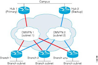
Now on to the Tunnels and the DMVPN networks itself. Here is the basic layout of the network:


As you can see, we are infact running two DMVPN networks, and each spoke as an interface to each network.

Lets do the Hubs first:

R1


interface Tunnel0
!IP of tunnel interface
ip address 172.12.123.1 255.255.255.0
!Stop IP from taking "shortcuts"
no ip redirects
ip mtu 1400
ip nhrp map multicast dynamic
!Unique to the network, same number on each hub,spoke
ip nhrp network-id 1
ip nhrp holdtime 450
ip tcp adjust-mss 1360
!Needed for EIGRP
no ip split-horizon eigrp 100
!Tweak EIGRP metrics to prefer this router
delay 1000
!Tunnels out interface
tunnel source FastEthernet1/0
!Set tunnel mode
tunnel mode gre multipoint
!Each tunnel has its own "password"
tunnel key 100000
!Add IPSec
tunnel protection ipsec profile TUN-PROFILE


Notice that R1 is the Hub spoke for 172.12.123.0/24 network

R2

!
interface Tunnel0
ip address 172.12.124.2 255.255.255.0
no ip redirects
ip mtu 1400
ip nhrp map multicast dynamic
ip nhrp network-id 2
ip nhrp holdtime 450
ip tcp adjust-mss 1360
no ip split-horizon eigrp 100
!tweak EIGRP metric so that R1 is preferred
delay 1050
tunnel source FastEthernet1/0
tunnel mode gre multipoint
!Password
tunnel key 100001
tunnel protection ipsec profile TUN-PROFILE
!


Now R20

First tunnel to join network 1

interface Tunnel0
ip address 172.12.123.20 255.255.255.0
ip mtu 1400
ip nhrp map 172.12.123.1 10.0.1.1
ip nhrp network-id 1
ip nhrp holdtime 450
ip nhrp nhs 172.12.123.1
ip tcp adjust-mss 1360
tunnel source FastEthernet1/0
tunnel destination 10.0.1.1
tunnel key 100000
tunnel protection ipsec profile TUN-PROFILE
!

Second Tunnel to join network 2

!
interface Tunnel1
ip address 172.12.124.20 255.255.255.0
ip mtu 1400
ip nhrp map 172.12.124.2 10.0.2.2
ip nhrp network-id 2
ip nhrp holdtime 450
ip nhrp nhs 172.12.124.2
ip tcp adjust-mss 1360
tunnel source FastEthernet1/0
tunnel destination 10.0.2.2
tunnel key 100001
tunnel protection ipsec profile TUN-PROFILE
!


Now R10

!network 1 -->
interface Tunnel0
ip address 172.12.123.10 255.255.255.0
ip mtu 1400
ip nhrp map 172.12.123.1 10.0.1.1
ip nhrp network-id 1
ip nhrp holdtime 450
ip nhrp nhs 172.12.123.1
ip tcp adjust-mss 1360
delay 1000
tunnel source FastEthernet1/0
tunnel destination 10.0.1.1
tunnel key 100000
tunnel protection ipsec profile TUN-PROFILE
!
!
!Network 2 ----->
interface Tunnel1
ip address 172.12.124.10 255.255.255.0
ip mtu 1400
ip nhrp map 172.12.124.2 10.0.2.2
ip nhrp network-id 2
ip nhrp holdtime 450
ip nhrp nhs 172.12.124.2
ip tcp adjust-mss 1360
tunnel source FastEthernet1/0
tunnel destination 10.0.2.2
tunnel key 100001
tunnel protection ipsec profile TUN-PROFILE
!


R11

!Network 1 --->
interface Tunnel0
ip address 172.12.123.11 255.255.255.0
ip mtu 1400
ip nhrp map 172.12.123.1 10.0.1.1
ip nhrp network-id 1
ip nhrp holdtime 450
ip nhrp nhs 172.12.123.1
ip tcp adjust-mss 1360
delay 1050
tunnel source FastEthernet1/0
tunnel destination 10.0.1.1
tunnel key 100000
tunnel protection ipsec profile TUN-PROFILE
!Network 2--->
interface Tunnel1
ip address 172.12.124.11 255.255.255.0
ip mtu 1400
ip nhrp map 172.12.124.2 10.0.2.2
ip nhrp network-id 2
ip nhrp holdtime 450
ip nhrp nhs 172.12.124.2
ip tcp adjust-mss 1360
tunnel source FastEthernet1/0
tunnel destination 10.0.2.2
tunnel key 100001
tunnel protection ipsec profile TUN-PROFILE
!


Now EIGRP network configuration, notice how we do not bring in the WAN network:
R1

router eigrp 100
network 1.1.1.1 0.0.0.0
network 172.12.123.0 0.0.0.255
network 192.168.1.0
no auto-summary
!

R2

router eigrp 100
network 2.2.2.2 0.0.0.0
network 172.12.124.0 0.0.0.255
network 192.168.1.0
no auto-summary
!

R20

router eigrp 100
network 20.20.20.20 0.0.0.0
network 172.12.123.0 0.0.0.255
network 172.12.124.0 0.0.0.255
network 192.168.3.0
no auto-summary
!

R10

!
router eigrp 100
network 10.10.10.10 0.0.0.0
network 172.12.123.0 0.0.0.255
network 172.12.124.0 0.0.0.255
network 192.168.2.0
no auto-summary
!

R11

!
router eigrp 100
network 11.11.11.11 0.0.0.0
network 172.12.123.0 0.0.0.255
network 172.12.124.0 0.0.0.255
network 192.168.2.0
no auto-summary
!


IPSec Configuration is almost identical for each router so here is just one example:

!
crypto isakmp policy 100
encr aes
authentication pre-share
group 2
crypto isakmp key letmein address 0.0.0.0 0.0.0.0
crypto isakmp keepalive 10
!
!
crypto ipsec transform-set TUN-TRANSFORM esp-aes esp-sha-hmac
!
crypto ipsec profile TUN-PROFILE
set transform-set TUN-TRANSFORM
!


And that should be it!

Here is a video of me with the lab,trying to break it!

DMVPN - High Availability - Testing Failure from Richard Vimeo on Vimeo.


Enjoy!

Thursday, 22 October 2009

DMVPN - Dual Hub and Dual Spoke with HSRP

After a short break I have some unique labs coming up. This is the first:

Wednesday, 30 September 2009

PIX/ASA Remote Access VPN with L2L VPN and Failover - How to

This is the practical for this lab:
here

There are a few things that we have already covered in other labs, Lan to Lan (or site to site) VPNs, NAT etc. However the main reason for this lab is three fold.

1) Setting up Active/Standby Failover
2) Setting up remote access IPSec VPN (in combination with L2L VPN)
3) Allowing the Remote User access to the Spoke Via Split Tunneling


When setting up failover, you should setup the first "unit" with a basic configuration, then use the LAN failover interface to sync the two up.


So here the basic config on FW1 (Primary unit):

Setting up the Interfaces:

interface Ethernet0
nameif Outside
security-level 0
ip address 10.0.0.1 255.255.255.0 standby 10.0.0.2
!
interface Ethernet1
nameif Inside
security-level 100
ip address 192.168.1.1 255.255.255.0 standby 192.168.1.2
!
interface Ethernet2
description trunk for failovers
!
interface Ethernet2.200
description LAN Failover Interface
vlan 200
!
interface Ethernet2.300
description STATE Failover Interface
vlan 300
!


Note: The failover interfaces cannot be on a shared interface.

Diagnostic ACL for pings etc:

access-list WAN_IN extended permit icmp any any


NAT

global (Outside) 1 interface
nat (Inside) 1 0.0.0.0 0.0.0.0


Default Gateway:

route Outside 0.0.0.0 0.0.0.0 10.0.0.4


Failover Config (Primary):

failover lan unit primary
failover lan interface lan-fo Ethernet2.200
failover polltime unit msec 200 holdtime msec 800
failover key letmeinfo
failover link state-fo Ethernet2.300
failover interface ip lan-fo 192.168.20.1 255.255.255.0 standby 192.168.20.2
failover interface ip state-fo 192.168.30.1 255.255.255.0 standby 192.168.30.2
failover lan enable
failover


Failover Config (Secondary):
This unit up until now had a blank configuration.

interface Ethernet2
description trunk for failovers
!
interface Ethernet2.200
description LAN Failover Interface
vlan 200
!
failover lan unit secondary
failover lan interface lan-fo Ethernet2.200
failover key letmeinfo
failover interface ip lan-fo 192.168.20.1 255.255.255.0 standby 192.168.20.2
failover lan enable
failover


At this point you should wait until the two configurations are synced up and the primary has taken the "active" role.

Setting up L2L VPN:

access-list NO-NAT extended permit ip 192.168.1.0 255.255.255.0 192.168.2.0 255.255.255.0
access-list IPSEC-TUN extended permit ip 192.168.1.0 255.255.255.0 192.168.2.0 255.255.255.0
nat (Inside) 0 access-list NO-NAT
crypto ipsec transform-set FW1-TRANSFORM esp-3des esp-sha-hmac
crypto map FW1 10 match address IPSEC-TUN
crypto map FW1 10 set peer 10.0.34.3
crypto map FW1 10 set transform-set FW1-TRANSFORM
crypto isakmp identity address
crypto isakmp enable Outside
crypto isakmp policy 100
authentication pre-share
encryption 3des
hash sha
group 2
tunnel-group 10.0.34.3 type ipsec-l2l
tunnel-group 10.0.34.3 ipsec-attributes
pre-shared-key letmeinl2l


Setting up the other end (FW3):
Basic setup:

!
interface Ethernet0
nameif outside
security-level 0
ip address 10.0.34.3 255.255.255.0
!
interface Ethernet1
nameif inside
security-level 100
ip address 192.168.2.1 255.255.255.0
!


VPN and ACLs:

access-list WAN_IN extended permit icmp any any
access-list NO-NAT extended permit ip 192.168.2.0 255.255.255.0 192.168.1.0 255.255.255.0
access-list IPSEC-TUN extended permit ip 192.168.2.0 255.255.255.0 192.168.1.0 255.255.255.0
global (outside) 1 interface
nat (inside) 0 access-list NO-NAT
nat (inside) 1 0.0.0.0 0.0.0.0
access-group WAN_IN in interface outside
route outside 0.0.0.0 0.0.0.0 10.0.34.4 1
crypto isakmp enable outside
crypto isakmp policy 100
authentication pre-share
encryption 3des
hash sha
group 2
tunnel-group 10.0.0.1 type ipsec-l2l
tunnel-group 10.0.0.1 ipsec-attributes
pre-shared-key letmeinl2l


Now, as it stands we should have an "Hub" and a "Spoke" set up with L2L vpn between the sites as well as their own wan (internet) traffic going out untouched.

Now Remote Access VPN:
Obviously LAN= 192.168.1.0/24 and VPN=10.1.1.0/24

access-list NO-NAT extended permit ip 192.168.1.0 255.255.255.0 10.1.1.0 255.255.255.0
access-list 101 extended permit tcp 10.1.1.0 255.255.255.0 192.168.1.0 255.255.255.0 eq www
access-list 101 extended permit tcp 10.1.1.0 255.255.255.0 192.168.1.0 255.255.255.0 eq ftp
access-list 101 extended permit tcp 10.1.1.0 255.255.255.0 192.168.1.0 255.255.255.0 eq telnet
access-list 101 extended permit icmp any any
aaa-server acs protocol radius
aaa-server acs (Outside) host 192.168.0.45
timeout 5
key letmein
ip local pool VPN-POOL 10.1.1.1-10.1.1.254
crypto ipsec transform-set VPN-TRANSFORM esp-3des esp-sha-hmac
crypto dynamic-map DYNA-MAP 1 set transform-set VPN-TRANSFORM
crypto dynamic-map DYNA-MAP 1 set security-association lifetime seconds 288000
crypto dynamic-map DYNA-MAP 1 set reverse-route
crypto map FW1 20 ipsec-isakmp dynamic DYNA-MAP
group-policy VPN-REMOTE internal
group-policy VPN-REMOTE attributes
dns-server value 208.67.222.222
vpn-idle-timeout none
vpn-tunnel-protocol IPSec
default-domain value cookie.local
tunnel-group VPN-REMOTE type remote-access
tunnel-group VPN-REMOTE general-attributes
address-pool VPN-POOL
authentication-server-group acs
default-group-policy VPN-REMOTE
tunnel-group VPN-REMOTE ipsec-attributes
pre-shared-key cisco123


Now the Split Tunnel and IPsec access to the Spoke:
FW-3:

access-list NO-NAT extended permit ip 192.168.2.0 255.255.255.0 10.1.1.0 255.255.255.0
access-list IPSEC-TUN extended permit ip 192.168.2.0 255.255.255.0 10.1.1.0 255.255.255.0


FW1:

same-security-traffic permit intra-interface
access-list NO-NAT extended permit ip 192.168.1.0 255.255.255.0 10.1.1.0 255.255.255.0
access-list IPSEC-TUN extended permit ip 10.1.1.0 255.255.255.0 192.168.2.0 255.255.255.0
access-list splittunnel standard permit 192.168.1.0 255.255.255.0
access-list splittunnel standard permit 192.168.2.0 255.255.255.0
group-policy VPN-REMOTE attributes
dns-server value 208.67.222.222
vpn-idle-timeout none
vpn-tunnel-protocol IPSec
split-tunnel-policy tunnelspecified
split-tunnel-network-list value splittunnel


And that is it! :P

If you need any info as to how to setup the client look here:
Setup VPN Client
The "group name" is VPN-REMOTE and the password is cisco123


Screenshot of it all working:

Tuesday, 29 September 2009

PIX/ASA Remote Access VPN with L2L VPN and Failover

Well I was going to do a nice multiple context PIX/ASA lab, but after playing around with GNS for a while and a good few hours into the lab I came to a brick wall.

The brick wall being that if you use multiple contexts you cannot use VPNs:
(http://www.cisco.com/en/US/docs/security/asa/asa80/configuration/guide/contexts.html#wp1116132)

So I created this lab instead:


If I get time ill upload the config tonight.

Monday, 28 September 2009

Load Balancing With HSRP

Got a nice simple lab for you today, load balancing with Hot Standby Routing Protocol.

HSRP is designed to increase the redundancy in LAN gateways. It does this by creating a Virtual MAC address and Virtual IP address.
One router of the "group" is elected as the "active" and the other the "standby", therefore once the "active" router, say for example gets accidentally turned off, the "standby" takes over.

Here is the picture of the lab:


Here is the important configuration:
R2

interface FastEthernet0/0
ip address 10.0.0.2 255.255.255.0
duplex auto
speed auto
!This is the virtual ip group 1
standby 1 ip 10.0.0.253
!I want this router to be the active router
standby 1 priority 12
!Take over active when your priority is higher
standby 1 preempt
!Any name here
standby 1 name Load1
!When this interface goes down, decrease my priority by 10
standby 1 track Serial0/0

!This is the virtual ip group 2
standby 2 ip 10.0.0.254
!I want this router to be the standby router
standby 2 priority 11
!Take over active when your priority is higher
standby 2 preempt
!Any name here
standby 2 name Load2
!When this interface goes down, decrease my priority by 10
standby 2 track Serial0/0


R3

interface FastEthernet0/0
ip address 10.0.0.3 255.255.255.0
duplex auto
speed auto
standby 1 ip 10.0.0.253
standby 1 priority 11
standby 1 preempt
standby 1 name Load1
standby 1 track Serial0/0
standby 2 ip 10.0.0.254
standby 2 priority 12
standby 2 preempt
standby 2 name Load2
standby 2 track Serial0/0


Note that for the load balancing to work 50% of the devices have 10.0.0.253 as their default gateway and the other 50% have 10.0.0.254.

Enjoy :)

Monday, 14 September 2009

Wednesday, 9 September 2009

MPLS VPN with MP-BGP

Currently working on a new lab, here is the setup:


More to follow...

Monday, 7 September 2009

Vyatta - Remote Access VPN Lab

Hi again this is the setup:


This lab details setting up NAT on vyatta routers, OpenVPN with TLS authentication, basic firewall setup and all the steps inbetween.

Here is the video:

Vyatta Remote Access OpenVPN lab with NAT and Firewall setup from Richard Vimeo on Vimeo.


Enjoy!

Tuesday, 1 September 2009

Vyatta Vmware Lab

Hi again,

Just to spice things up a little I thought I would do a lab on vyatta, so I dug out part of an old lab, and presto - A Vyatta based OSPF 3 site lab:


and this is how I did it:

Part 1:

Vyatta Vmware Lab Part1 from Richard Vimeo on Vimeo.


Part2

Vyatta Vmware Lab Part2 from Richard Vimeo on Vimeo.


Enjoy!

Monday, 31 August 2009

PIX/ASA Site-to-Site (L2L) VPN with DMZ-Howto

Ok this the how to for this lab: here


So lets start from the Remote Office "FW2"

First we need to set up ASA:
FW2

!
interface Ethernet0
nameif Outside
security-level 0
ip address 10.0.2.2 255.255.255.0
!
interface Ethernet1
nameif DMZ
security-level 50
ip address 192.168.20.2 255.255.255.0
!
interface Ethernet2
nameif Inside
security-level 100
ip address 192.168.2.2 255.255.255.0
!


Now NAT:

nat (Inside) 1 0.0.0.0 0.0.0.0
!Most people might like global (Outside) 1 interface instead
global (Outside) 1 10.0.2.50


Notice the "1" above, that ties the entrys together essentially saying on "these people on the inside (0.0.0.0) (everyone) are translated to this address "10.0.2.50" on the outside.

Now for testing we want to allow ICMP to the firewall

access-list WAN_IN extended permit icmp any any


Then assign it to an interface:

access-group WAN_IN in interface Outside


Add a default route:

route Outside 0.0.0.0 0.0.0.0 10.0.2.10 1


Ok we now have "internet access"

Next we need to setup the web server(192.168.20.100) with 1-to-1 nat:

nat (DMZ) 2 0.0.0.0 0.0.0.0
global (Outside) 2 10.0.2.100
static (DMZ,Outside) 10.0.2.100 192.168.20.100 netmask 255.255.255.255


Now NAT is setup, we actually need to let something through:

access-list WAN_IN extended permit tcp any host 10.0.2.100 eq telnet
access-list WAN_IN extended permit tcp any host 10.0.2.100 eq http


ok that was easy :)

Now for the HQ site:
First setup the pix:
FW1

interface Ethernet0
nameif outside
security-level 0
ip address 10.0.1.1 255.255.255.0
!
interface Ethernet1
nameif inside
security-level 100
ip address 192.168.1.1 255.255.255.0
!


Now NAT for FW1:

nat (inside) 1 0.0.0.0 0.0.0.0
global (outside) 1 interface


Ok now the tough part, actually this should be the easy part as we have done IPSec to death so far on the blog, and although the syntax looks different, actually typing it is pretty much the same as IOS.

One FW2
Set up an ISAKMP Policy:

crypto isakmp policy 100
authentication pre-share
encryption aes
hash sha
group 2
lifetime 86400


Then a Transform Set:

crypto ipsec transform-set FW1-TRANSFORM esp-aes esp-sha-hmac


Specify the traffic we dont want NAT applied too:

access-list NO-NAT extended permit ip 192.168.1.0 255.255.255.0 192.168.2.0 255.255.255.0
nat (inside) 0 access-list NO-NAT


The 0 indicates "dont NAT this"

Bring it all together with a crypto map:

access-list IPSEC-TUN extended permit ip 192.168.1.0 255.255.255.0 192.168.2.0 255.255.255.0
crypto map FW1 10 match address IPSEC-TUN
crypto map FW1 10 set peer 10.0.2.2
crypto map FW1 10 set transform-set FW1-TRANSFORM


Enable it on an interface:

crypto map FW1 interface outside


Add a tunnel group (if it is not already done for you)

tunnel-group 10.0.2.2 type ipsec-l2l
tunnel-group 10.0.2.2 ipsec-attributes
pre-shared-key letmein


Actually allow ISAKMP to connect to the outside interface:

crypto isakmp enable outside


Then the reverse/same on FW1:

access-list IPSEC-TUN extended permit ip 192.168.1.0 255.255.255.0 192.168.2.0 255.255.255.0
access-list NO-NAT extended permit ip 192.168.1.0 255.255.255.0 192.168.2.0 255.255.255.0
nat (inside) 0 access-list NO-NAT
crypto ipsec transform-set FW1-TRANSFORM esp-aes esp-sha-hmac
crypto map FW1 10 match address IPSEC-TUN
crypto map FW1 10 set peer 10.0.2.2
crypto map FW1 10 set transform-set FW1-TRANSFORM
crypto map FW1 interface outside
crypto isakmp enable outside
crypto isakmp policy 100
authentication pre-share
encryption aes
hash sha
group 2
lifetime 86400
tunnel-group 10.0.2.2 type ipsec-l2l
tunnel-group 10.0.2.2 ipsec-attributes
pre-shared-key *
prompt hostname context


Done!

Pix/ASA does alot for you in l2l ipsec vpns..and they still dont call it "easy vpn" :)

Thursday, 27 August 2009

PIX/ASA Site-to-Site (L2L) VPN with DMZ

Something a little different PIX!

Heres the lab I've done and I will up the configs tomorrow.

First in GNS:


Then Opendraw:

L2TPv3 over IPSec with VLANS-How to

This is the practical of this lab: here

The idea of this lab is to bridge the local lan across the internet or another network you do not control to another lan, matching lan.

In this example we have 3 sites. Site 1 (which is the head office) with a server for each site (server 2 and server 3). L2TPv3 works by taking the frame recieved on its lan interface wraps it up int L2TP goodness and off it goes.

Again what makes this cool is that the workstations (PC2 and PC3) have no idea that the Servers are at another site.

Ok now your up to speed...:


First each router has a default route to R0
R2:

ip route 0.0.0.0 0.0.0.0 10.0.20.10

R3:

ip route 0.0.0.0 0.0.0.0 10.0.30.10


R1:

ip route 0.0.0.0 0.0.0.0 10.0.10.10


Ok now to the Layer 2 setup, as GNS can not do Switches (well properly anyway) you have to use a Cisco 3725 with a 16 port Ethernet Switch card.

So firstly the trunks on R1, R2 and R3

R1

!
interface FastEthernet1/1.200
encapsulation dot1Q 200
!
interface FastEthernet1/1.300
encapsulation dot1Q 300

!

R2

!
interface FastEthernet1/1.200
encapsulation dot1Q 200
!

R3

!
interface FastEthernet1/1.300
encapsulation dot1Q 300
!


Then setting up the switch:
Switch1

interface FastEthernet1/1
switchport mode trunk
!
interface FastEthernet1/2
switchport access vlan 200
!
interface FastEthernet1/3
switchport access vlan 300
!


Switch2

!
interface FastEthernet1/1
switchport mode trunk
!
interface FastEthernet1/2
switchport access vlan 200
!


Switch3

!
interface FastEthernet1/1
switchport mode trunk
!
interface FastEthernet1/2
switchport access vlan 300
!


I'll leave the setting up of the IP addresses to you :)

Ok now to the fun stuff the L2TPv3 setup:

R1

l2tp-class l2tp-defaults
retransmit initial retries 30
cookie size 8
!
!
pseudowire-class VLANS
encapsulation l2tpv3
protocol none
ip local interface FastEthernet1/0
!


R2

l2tp-class l2tp-defaults
retransmit initial retries 30
cookie size 8
!
!
pseudowire-class VLAN200
encapsulation l2tpv3
protocol none
ip local interface FastEthernet1/0
!


R3

l2tp-class l2tp-defaults
retransmit initial retries 30
cookie size 8
!
pseudowire-class VLAN300
encapsulation l2tpv3
protocol none
ip local interface FastEthernet1/0
!


Now part two of the setup, which is the actual pseudeowire!
R1

!
interface FastEthernet1/1.200
encapsulation dot1Q 200
! The vc 200 here is not used...call it anything you like!
xconnect 10.0.20.2 200 encapsulation l2tpv3 manual pw-class VLANS
! This id is important 102 and 202 must be swaped on the other end
l2tp id 102 202
! "remote" is data sent
! "local" is data expected to be recieved.
! Therefore 221200 is Router 2 2 Router 1 VLAN 200 (R22R1VLAN200)
! Just makes it easier for you, but you can do any number as long as
! it is flipped
l2tp cookie local 4 221200
l2tp cookie remote 4 122200
l2tp hello l2tp-defaults
!
interface FastEthernet1/1.300
encapsulation dot1Q 300
xconnect 10.0.30.3 300 encapsulation l2tpv3 manual pw-class VLANS
l2tp id 103 303
l2tp cookie local 4 321300
l2tp cookie remote 4 123300
l2tp hello l2tp-default
s
!


Then the spokes:
R2

!
interface FastEthernet1/1.200
encapsulation dot1Q 200
ip virtual-reassembly
xconnect 10.0.10.1 200 encapsulation l2tpv3 manual pw-class VLAN200
l2tp id 202 102
l2tp cookie local 4 122200
l2tp cookie remote 4 221200
l2tp hello l2tp-defaults
!


R3

interface FastEthernet1/1.300
encapsulation dot1Q 300
ip virtual-reassembly
xconnect 10.0.10.1 300 encapsulation l2tpv3 manual pw-class VLAN300
l2tp id 303 103
l2tp cookie local 4 123300
l2tp cookie remote 4 321300
l2tp hello l2tp-defaults
!


You can now test that it works, however at the moment it is all unencrypted!

Therefore encryption;
R1

!
crypto isakmp policy 100
encr 3des
authentication pre-share
group 2
crypto isakmp key letmein address 0.0.0.0 0.0.0.0
!
!
crypto ipsec transform-set R1-TRANSFORM esp-3des esp-sha-hmac
!
crypto map R12R2R3 100 ipsec-isakmp
set peer 10.0.30.3
set transform-set R1-TRANSFORM
match address 110
crypto map R12R2R3 200 ipsec-isakmp
set peer 10.0.20.2
set transform-set R1-TRANSFORM
match address 100
!
access-list 100 permit ip host 10.0.10.1 host 10.0.20.2
access-list 110 permit ip host 10.0.10.1 host 10.0.30.3
!
!
interface FastEthernet1/0
ip address 10.0.10.1 255.255.255.0
ip virtual-reassembly
duplex auto
speed auto
crypto map R12R2R3
!


R2

!
crypto isakmp policy 100
encr 3des
authentication pre-share
group 2
crypto isakmp key letmein address 0.0.0.0 0.0.0.0
!
!
crypto ipsec transform-set R2-TRANSFORM esp-3des esp-sha-hmac
!
crypto map R22R1 100 ipsec-isakmp
set peer 10.0.10.1
set transform-set R2-TRANSFORM
match address 100
!
!
access-list 100 permit ip host 10.0.20.2 host 10.0.10.1
!
!
interface FastEthernet1/0
ip address 10.0.20.2 255.255.255.0
ip virtual-reassembly
duplex auto
speed auto
crypto map R22R1
!


R3

!
crypto isakmp policy 100
encr 3des
authentication pre-share
group 2
crypto isakmp key letmein address 0.0.0.0 0.0.0.0
!
!
crypto ipsec transform-set R3-TRANSFORM esp-3des esp-sha-hmac
!
crypto map R32R1 100 ipsec-isakmp
set peer 10.0.10.1
set transform-set R3-TRANSFORM
match address 100
!
access-list 100 permit ip host 10.0.30.3 host 10.0.10.1
!
!
interface FastEthernet1/0
ip address 10.0.30.3 255.255.255.0
ip virtual-reassembly
duplex auto
speed auto
crypto map R32R1
!


Bit of a sledgehammer approach to encryption as everything will be wrapped up in ESP, however if you wish to do this for just L2TP then an ACL for UDP 1701 will do the job nicely.

Done!